

A flush toilet
A toilet and flushing technology, used in flushing toilets, water supply devices, buildings, etc., can solve problems such as poor customer experience and difficulty in discharging toilets, and achieve the goal of improving aesthetics, preventing splashing, and improving flushing ability. Effect
- Summary
- Abstract
- Description
- Claims
- Application Information
AI Technical Summary
Problems solved by technology
Method used
Image

Examples
Embodiment Construction
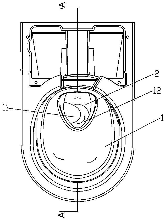
[0031] The present invention will be further described below in conjunction with the accompanying drawings. For the convenience of description, the positional relationship of "front, back, left, and right" in the following descriptions is as follows: the toilet is generally placed close to the wall, and the water supply pipeline is connected from the wall. Elicited, seen when the body is close to the toilet and looking down at the toilet figure 1 View, definition: figure 1 The "lower" in is the "front" in the following descriptions, figure 1 The "upper" in is the "back" in the following descriptions, figure 1 The "left" in is the "left" in the following descriptions, figure 1 The "right" in is the "right" in the following description.
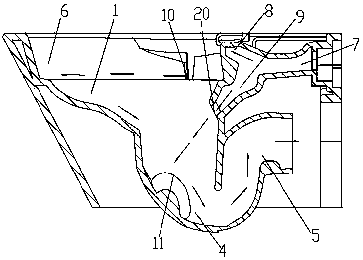
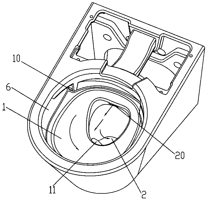
[0032] Such as figure 1 As shown, the flush toilet has a cleansing face 1, and a water trap 2 is arranged at the bottom of the cleansing face 1, and the water trap 2 has a receiving portion 4 extending downward from the bottom of the cleans...
PUM
 Abstract
Description
Claims
Application Information