

Liquid evaporation device and process
A technology of liquid evaporation and gas heating device, applied in evaporation device, evaporation, evaporator accessories and other directions, can solve the problems of large equipment investment, low evaporation efficiency of evaporation process, inability to use materials to concentrate or crystallize, etc., to achieve high evaporation efficiency, The effect of saving film-forming energy consumption and equipment cost
Pending Publication Date: 2018-08-28
MEIQING TECH BEIJING CO LTD
View PDF0 Cites 3 Cited by
- Summary
- Abstract
- Description
- Claims
- Application Information
AI Technical Summary
Problems solved by technology
[0006] In view of the above-mentioned situations that the existing evaporation process that does not make the material boil has low evaporati
Method used
View moreImage
Smart ImageViewing Examples

Examples
 PUM
 Abstract
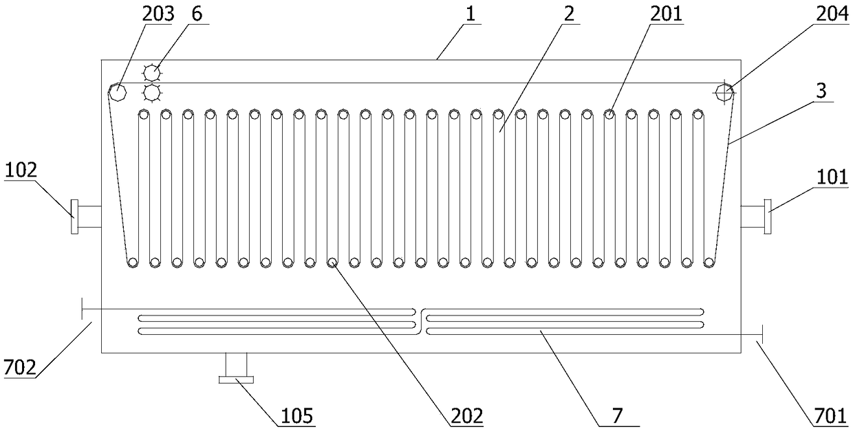
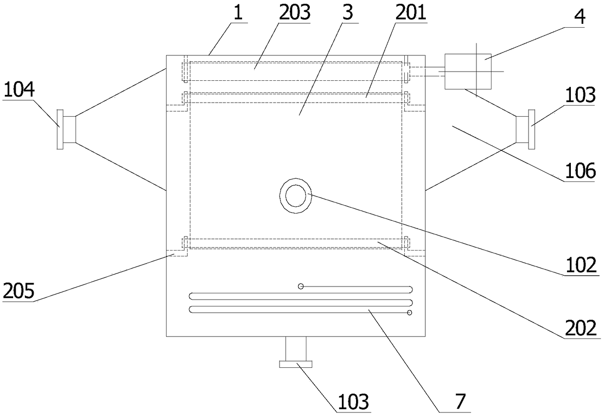
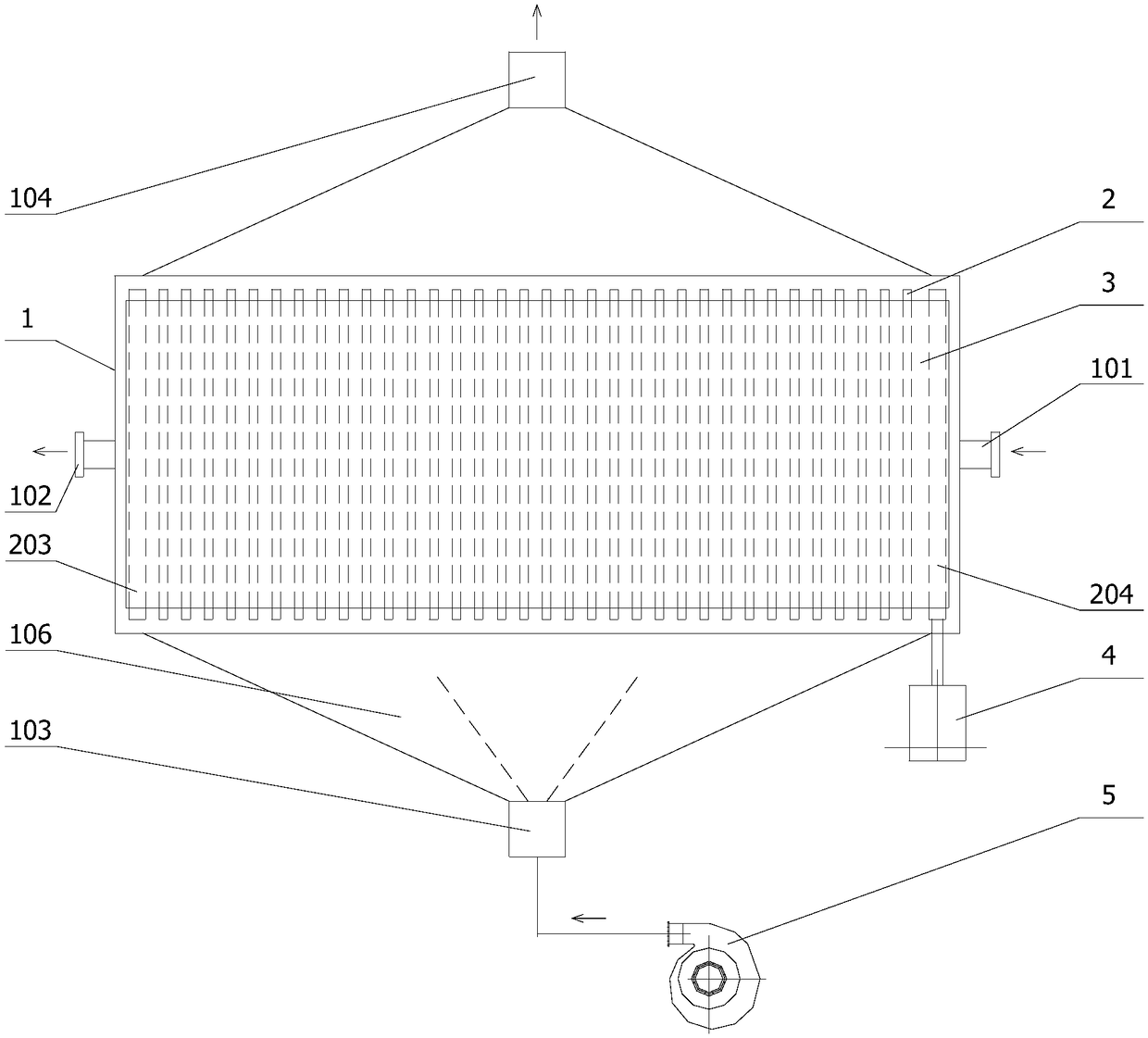
The invention discloses a low-temperature evaporation device and process. The device includes a housing, a roller shaft and a soaking band; a liquid inlet and a liquid outlet are formed in the housing; the roller shaft includes an upper roller shaft body, a lower roller shaft body, a tightening roller shaft body, a driving roller shaft body and a supporting piece connected to the housing; the upper roller shaft body, the lower roller shaft body, the tightening roller shaft body and the driving roller shaft body are distributed parallelly in the housing in the same direction; the soaking band penetrates through the upper roller shaft body, the lower roller shaft body, the tightening roller shaft body and the driving roller shaft body to form a closed loop; the lower roller shaft body is completely or partially soaked under the liquid level of a to-be-evaporated feed liquid, it is ensured that the portion, on the lower roller shaft body, of the soaking band is in contact with the to-be-evaporated feed liquid, and therefore a layer of liquid membrane is formed on the outer surface of the soaking band when a liquid material is in contact with the outer surface of the soaking band. By designing the soaking band for penetrating through the whole device body vertically, the superficial area of an available liquid membrane per unit volume of an evaporator is large, and the evaporationefficiency of the evaporator of equipment is greatly improved. By designing the soaking band for circularly rotating, the liquid membrane can be conveniently maintained on the surface of the soaking band, and energy consumption for forming the membrane is reduced.
Description
technical field [0001] The present invention generally relates to a liquid evaporation technology, in particular to a process and equipment for evaporative concentration or crystallization of liquids below the boiling point, which can be used for evaporative concentration of liquid materials (such as waste water concentration reduction or zero discharge) , can also be used to extract solutes from solutions in the form of crystallization, and can also be used for seawater desalination. The invention belongs to the fields of chemical industry and water treatment. Background technique [0002] For occasions where liquid materials (such as seawater and waste water) need to be evaporated and concentrated or crystallized to extract the dissolved solids, the current common method is to heat the liquid to its boiling point, or take decompression measures at the same time to make it boil, In this way, concentrated liquid or crystals of dissolved solids (such as concentrated seawater...
Claims
Login to View More Application Information
Patent Timeline
 IPC IPC(8): B01D1/14B01D1/30B01D3/00C02F1/10C02F103/08
CPCB01D1/0005B01D1/14B01D1/30B01D3/00B01D3/008C02F1/048C02F1/10C02F2103/08
Inventor靳兆融
OwnerMEIQING TECH BEIJING CO LTD