Methods and apparatus for clutch and brake drag reduction using springs

A technology of clutches and clutch components, applied to parts of brakes, clutches, friction clutches, etc., can solve problems such as low mechanical efficiency

Active Publication Date: 2018-08-28
TOYOTA JIDOSHA KK
View PDF7 Cites 2 Cited by
  • Summary
  • Abstract
  • Description
  • Claims
  • Application Information

AI Technical Summary

Problems solved by technology

Power loss due to the drag of an open clutch can be a significant source of mechanical inefficiency in automotive transmissions

Method used


Image

  • Methods and apparatus for clutch and brake drag reduction using springs
  • Methods and apparatus for clutch and brake drag reduction using springs
  • Methods and apparatus for clutch and brake drag reduction using springs

Examples


Embodiment Construction

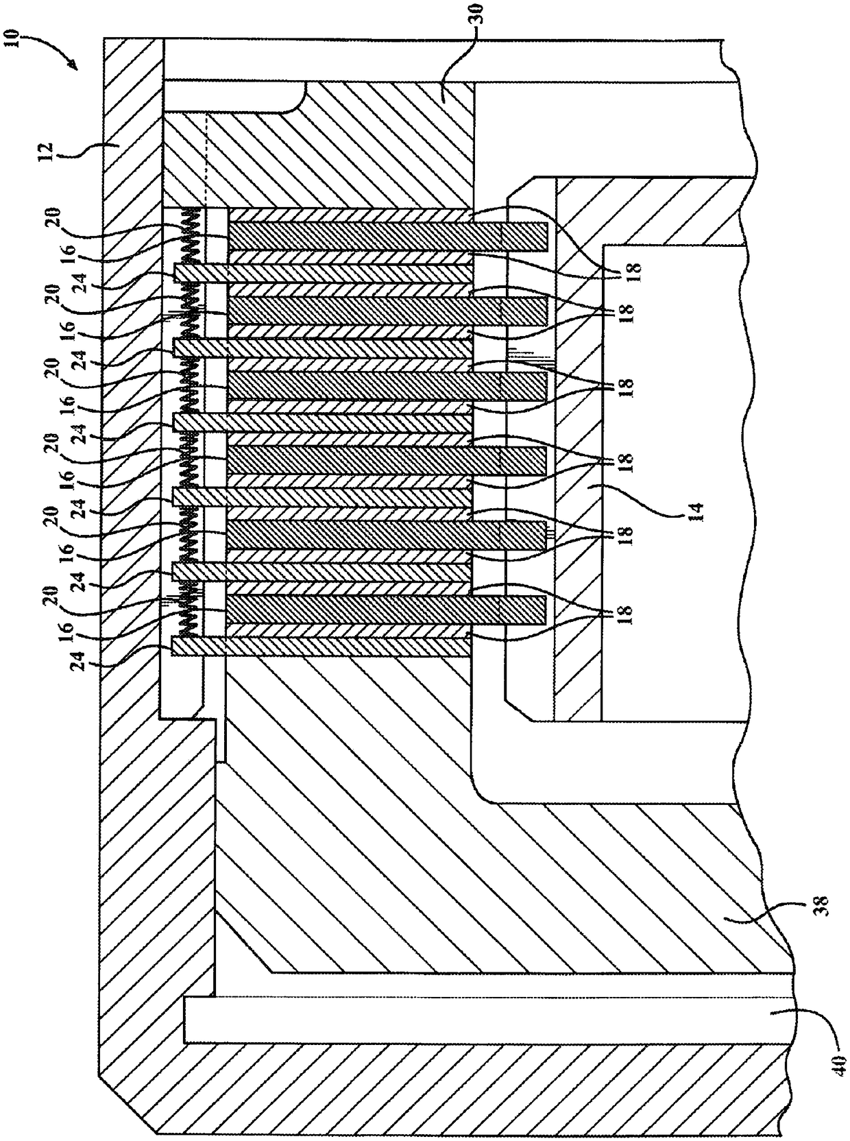
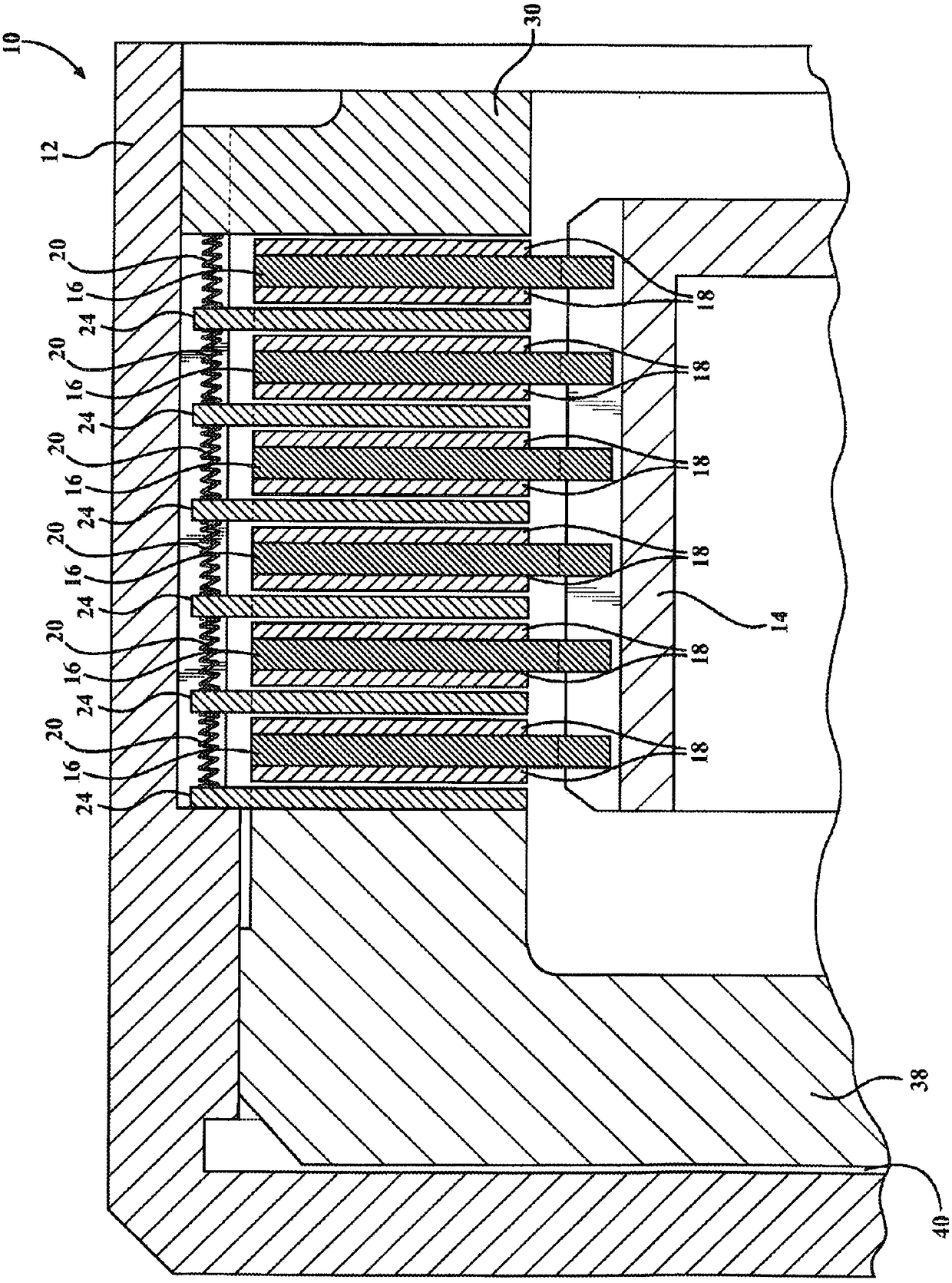
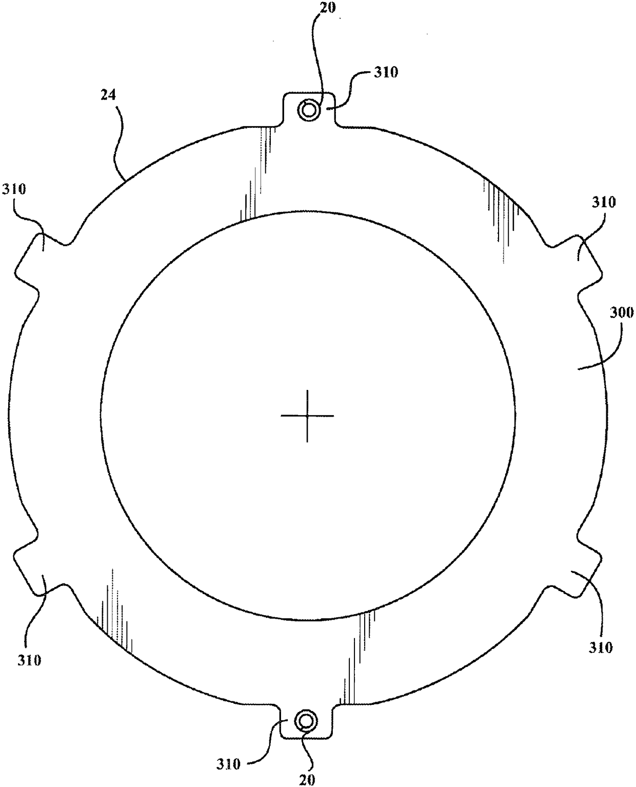
[0016] Embodiments described herein relate to clutch assemblies and separator plates for clutch assemblies. Each of the separator plate embodiments includes one or more springs therein. As used herein, a spring may include any mechanism (eg, a helical coil or mesh) or material (eg, rubber) that can be compressed or pulled and then return to its previous shape. The spring may be mounted on or in the first divider plate adjacent to the second divider plate. This arrangement creates a repulsive separation force between adjacent divider panels. When the clutch pack is in the open condition, this disengagement force pushes the adjacent separator plates apart, thereby helping to separate the separator plates from the clutch friction plates when the clutch is disengaged.

[0017] The present disclosure is described in detail with reference to the accompanying drawings which form a part hereof. In the drawings, similar reference symbols typically identify similar components, unless...


PUM


Abstract

Described herein are various embodiments of a clutch assembly and separator plates for a clutch assembly. The clutch assembly may comprise a first separator plate; a second separator plate; and a spring coupled to the first separator plate and contacting the second separator plate, such that when compressed the spring applies a repulsive force separating the first separator plate and the second separator plate.

Description

technical field [0001] The present invention relates to brake and clutch assemblies, and more particularly to methods and apparatus for reducing drag in clutches and brakes using springs. Background technique [0002] Known conventional clutch assemblies may include a plurality of friction plates and a separator plate positioned between each adjacent pair of friction plates. When the friction and separator plates contact, or "engage," one another, a power path is established for transmitting torque to a load (eg, the wheels of a vehicle). When the clutch is disengaged or opened, it is desirable to ensure that the separator plate separates from (and remains spaced from) the friction plates in order to minimize clutch drag. Clutch drag can occur in an open clutch when one or more separator plates fail to disengage from the associated friction plates or when the gap between adjacent plates is small, causing fluid layers that separate adjacent plates internal resistance. Powe...

Claims


Application Information

Patent Timeline
Patent Type & Authority Applications(China)
IPC IPC(8): F16D13/58F16D65/00
CPCF16D13/58F16D65/005F16D13/69F16D25/0638F16D25/12F16D13/52
Inventor L·A·里佩尔迈耶安井宏树
Owner TOYOTA JIDOSHA KK
Why Eureka
Try Eureka