Tyre mold

A technology of tire molds and mold shells, which is applied in the field of tire manufacturing, and can solve problems such as easy delamination and damage, unusability, and impact on tire wear resistance, so as to avoid extrusion or other damage, facilitate wiring and dismantling, and prolong service life The effect of longevity

Active Publication Date: 2018-12-21
HIMILE MECHANICAL SCI & TECH (SHANDONG) CO LTD
View PDF3 Cites 0 Cited by
  • Summary
  • Abstract
  • Description
  • Claims
  • Application Information

AI Technical Summary

Problems solved by technology

[0002] When producing existing tires, it is necessary to strictly control the temperature and time of tire vulcanization. Poor control of the vulcanization temperature of green tire blanks will lead to tire scrapping and affect the qualified rate of tire quality
The vulcanization temperature is low, under the same time, it will produce undersulfur, undersulfur tire rubber reaction is not sufficient, the physical properties are poor, when the undersulfur is serious, it will be sticky, and it cannot be used. Poor, and easy to delaminate and damage; high vulcanization temperature, under the same time pressure, oversulfurization will occur, oversulfurized tire rubber will become brittle, poor wear resistance when used, and the phenomenon of chipping and chipping will also occur
[0003] Existing tire molds basically do not have the function of measuring the temperature of the mold. Even if there is, only a wire hole for temperature measurement of a tire is reserved on the mold. However, when the tire temperature is detected through the wire hole, it is necessary Inserting the temperature detection piece into the tire will damage the surface of the tire
The mold can only be used for temperature measurement. After the temperature measurement is completed, it cannot be used for vulcanization of normal tires.
However, when the temperature measurement line is arranged, it is not necessary to consider the non-temperature measurement working conditions of the mold, nor does it consider the influence of the mold opening and closing action on the line.

Method used


Image

  • Tyre mold
  • Tyre mold
  • Tyre mold

Examples


Embodiment 1

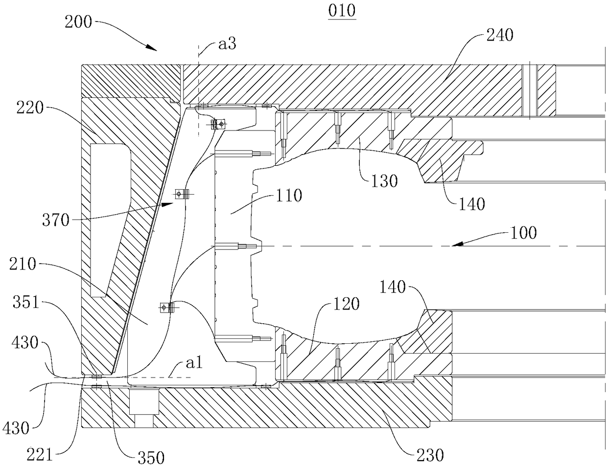
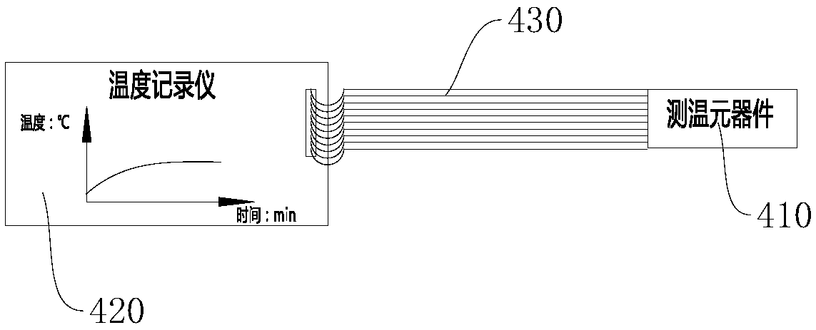
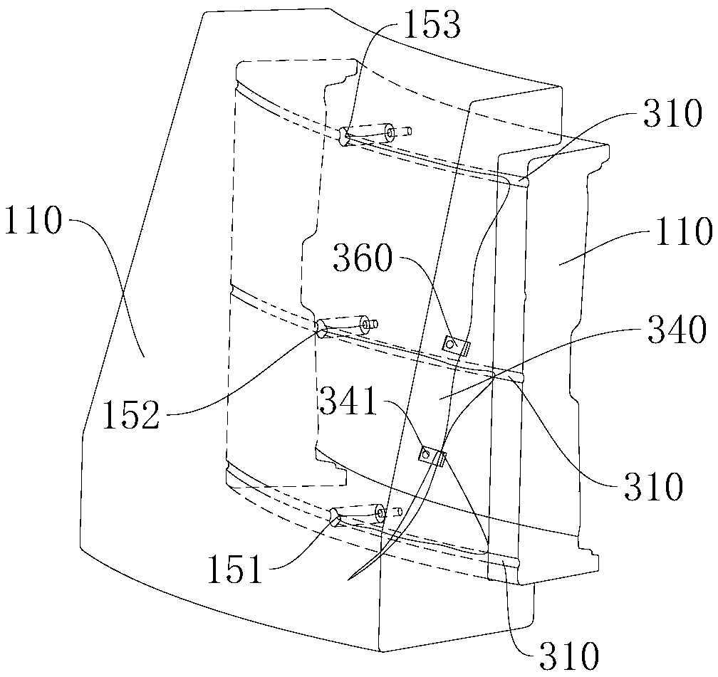
[0045] figure 1 A schematic diagram of the overall structure of the tire mold 010 provided in this embodiment. Please refer to figure 1, the present embodiment provides a tire mold 010 , which includes a mold shell assembly 200 and a cavity assembly 100 disposed in the mold shell assembly 200 . The cavity assembly 100 includes an upper side plate 130 and a plurality of pattern blocks 110 arranged along the circumference of the upper side plate 130, at least one of the pattern blocks 110 or the upper side plate 130 is opened with a temperature measuring hole 150, and the temperature measuring hole 150 is set There is a temperature measuring element 410 . The tire mold 010 is equipped with a wire-passing groove connected to the temperature measuring hole 150, and the temperature-measuring wire 430 of the temperature-measuring element 410 passes through the wire-passing groove to be led out of the cavity assembly 100, realizing the tire mold 010 preheating and tire vulcanizatio...


PUM


Abstract

The invention relates to the technical field of tyre manufacturing, and aims at providing a tyre mold. The provided tyre mold comprises a mold shell assembly and a cavity assembly arranged in the moldshell assembly. The cavity assembly comprises an upper side plate and a plurality of pattern blocks, wherein at least one of the pattern blocks or the upper side plate is provided with a temperaturemeasuring hole internally provided with a temperature measuring element. The tyre mold is provided with a wire passing groove communicating with the temperature measuring hole. A temperature measuringwire of the temperature measuring element penetrates through the wire passing groove and is guided out of the cavity assembly. The wire passing groove for the temperature measuring wire to be guidedout is formed, the wiring manner of the temperature measuring wire is reasonably set, influences of the temperature measuring wire on the work of the tyre mold are avoided, and wire arrangement and wire dismounting are convenient. Meanwhile, the problem that in the temperature measuring wire usage process, the temperature measuring wire is subjected to extrusion or other damage is solved, and accordingly the service life of the tyre mold is prolonged.

Description

technical field [0001] The invention relates to the technical field of tire manufacturing, in particular to a tire mold. Background technique [0002] During the production of existing tires, the temperature and time of tire vulcanization need to be strictly controlled. If the temperature of green tire green tires is not well controlled, the tires will be scrapped and the qualified rate of tire quality will be affected. The vulcanization temperature is low, under the same time, it will produce undersulfur, undersulfur tire rubber reaction is not sufficient, the physical properties are poor, when the undersulfur is serious, it will be sticky, and it cannot be used. Poor, and easy to delaminate and damage; high vulcanization temperature, under the same time pressure, oversulfurization will occur, and oversulfurized tire rubber will become brittle, and it also has poor wear resistance during use, and it will also cause chipping and chipping. [0003] Existing tire molds basica...

Claims


Application Information

Patent Timeline
IPC IPC(8): B29D30/06
CPCB29D30/0606B29D30/0662B29D2030/0607
Inventor 刘志兰张伟赵阳杜平于泳赵鹏
Owner HIMILE MECHANICAL SCI & TECH (SHANDONG) CO LTD
Why Eureka
Try Eureka