Spotlighting LED lamp

A technology of LED lamps and lampposts, applied in the direction of light source, electric light source, light source fixation, etc., can solve the problems of poor focusing effect, light source position change, etc., and achieve the effect of simple and fast adjustment method

Active Publication Date: 2018-12-21
安徽省富鑫雅光电科技有限公司
View PDF6 Cites 0 Cited by
  • Summary
  • Abstract
  • Description
  • Claims
  • Application Information

AI Technical Summary

Problems solved by technology

[0003] The purpose of the present invention is to provide a concentrating LED lamp to solve the problem that when the LED lamp proposed in the above background technology needs to be replaced, the position of the light source changes and the concentrating effect becomes poor; for different tasks, in the prior art, only The problem of adjusting the light by changing the brightness of the light

Method used


Image

  • Spotlighting LED lamp
  • Spotlighting LED lamp
  • Spotlighting LED lamp

Examples


Embodiment 1

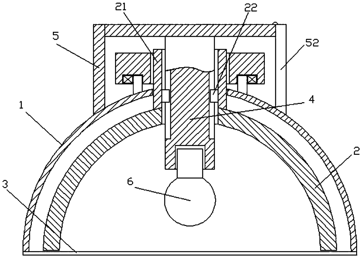
[0022] A spotlight LED lamp, comprising a shell 1, the shell 1 is hemispherical as a whole, a cover plate 3 is provided at the bottom of the shell 1, the cover plate 3 is a transparent glass cover plate, and a cover is provided on the top of the shell 1 Cover 5, the cover 5 is cylindrical as a whole, the lower end of the cover 5 is fixedly connected to the outer surface of the housing 1, the housing 1 is provided with a lamp post 4, and the lamp post 4 is vertically arranged in the middle of the housing 1 , and the protruding end of the lamp post 4 is fixedly connected to the lower surface of the top of the cover 1, and the lower end of the lamp post 4 is connected with an LED lamp 6, and a rotating assembly is arranged inside the cover 5, and the rotating assembly is connected with the shell 1, A lampshade 2 is arranged inside the housing 1, and the lampshade 2 is matched with the rotating assembly, and the inner wall of the lampshade 2 is coated with reflective material. Whe...

Embodiment 2

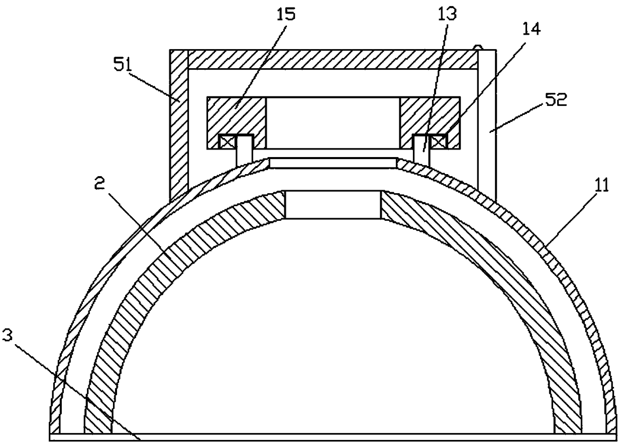
[0028] Different from the above embodiments, in this embodiment, the cover 5 includes a fixed cover 51 and a second movable cover 53, and the fixed cover 51 is mated with the second movable cover 53, and the The fixed cover 51 is cylindrical as a whole, and the bottom of the fixed cover 51 is fixedly connected to the outer surface of the housing 11. The second movable cover 53 is a semi-circular ring, and slots are provided at both ends of the top of the fixed cover 51. 54 , the two ends of the top of the second movable cover 53 are provided with insertion rods 55 , and the slots 54 are engaged with the insertion rods 55 . When the rotating plate 15 needs to be adjusted, the second movable cover 53 can be pulled out to adjust the rotating plate 15 , and the second movable cover 53 can be fastened after the adjustment is completed.

[0029] Specific working principle and steps: When the LED lamp 6 needs to be replaced, after the LED lamp 6 is connected to the lamp post 4, the p...


PUM


Abstract

The invention discloses a spotlighting LED lamp comprising a shell. A cover plate is arranged at the bottom of the shell and is a transparent glass cover plate. A cover lid is arranged at the top of the shell and is overall cylindrical. The lower end of the cover lid is fixedly connected with the outer surface of the shell. A lamp pole is arranged in the shell and is vertically arranged in the middle of the shell, and the stretching end of the lamp pole is fixedly connected with the lower surface of the top of the cover lid. An LED lamp body is connected to the lower end of the lamp pole. A rotary assembly is arranged in the cover lid and is in matched connection with the shell. A lampshade is arranged in the shell and is in matched connection with the rotary assembly. The inner wall of the lampshade is coated with reflection materials. The problems that when an LED lamp needs to be replaced, the position of a light source changes, the spotlighting effect becomes poor, and in the priorart, light rays are adjusted only by changing the luminance of the light rays for different work are solved.

Description

technical field [0001] The invention relates to the technical field of LED lamps, in particular to a spotlight LED lamp. Background technique [0002] LED lights are widely used in daily life. When the LED lights need to be replaced, the position of the light source in the lampshade may change. In addition, it is necessary to adjust the light for different tasks. For example, when disassembling some precision instruments, the light needs to be concentrated, but when doing daily reading and work, the light does not need to be too concentrated. In the prior art, the light can only be adjusted by changing the brightness of the light. When the brightness of the light is high, it will consume more electricity. Contents of the invention [0003] The purpose of the present invention is to provide a concentrating LED lamp to solve the problem that when the LED lamp proposed in the above background technology needs to be replaced, the position of the light source changes and the c...

Claims


Application Information

Patent Timeline
Patent Type & Authority Applications(China)
IPC IPC(8): F21S8/00F21V7/04F21V7/28F21V14/04F21V15/01F21Y115/10
CPCF21S8/00F21V7/045F21V14/04F21V15/01F21Y2115/10F21V7/28
Inventor 刘承汐
Owner 安徽省富鑫雅光电科技有限公司
Why Eureka
Try Eureka