Particle imaging method

A technology of particle imaging and velocity imaging, which is applied in the field of photoreaction of macromolecular clusters, can solve problems such as difficult cooling of cluster ions, influence on experimental results, and precise control of measurement of difficult-to-dope molecules, so as to improve photoreaction efficiency, Short cooldown effect

Pending Publication Date: 2019-01-01
JINHUA VOCATIONAL TECH COLLEGE
View PDF0 Cites 2 Cited by
  • Summary
  • Abstract
  • Description
  • Claims
  • Application Information

AI Technical Summary

Benefits of technology

This patented technology allows for precise control over how small molecules react when mixed together at specific locations on surfaces or inside cells. It also makes it easier to collect data from these sites by measuring them accurately during their formation process.

Problems solved by technology

This patented technical solution involves creation of small particles called dopant atoms (dopants) within specific chemical groups on an atomized material. These tiny deoxygen centers have potential applications for various fields like medicine, electronics, materials storage, etc., but there may also exist new uses related thereto.

Method used


Image

  • Particle imaging method
  • Particle imaging method

Examples


Embodiment Construction

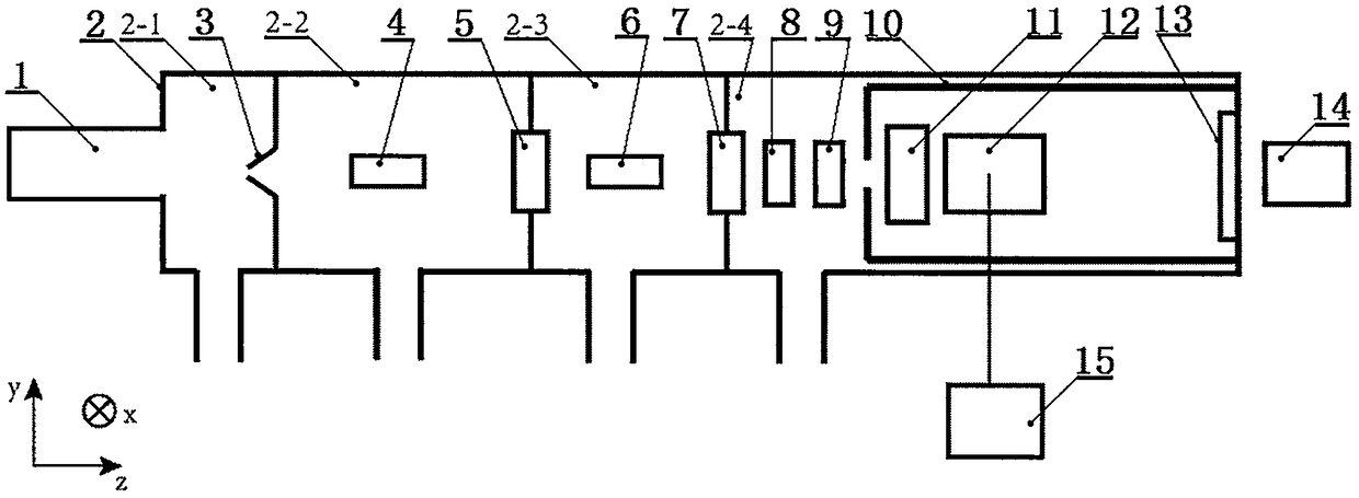
[0029] Such as figure 1 It is a schematic diagram of the present invention, and xyz is a three-dimensional space coordinate system, including a cluster source (1), a vacuum chamber (2), a shunt (3), an ion lens I (4), a gate valve I (5), an ion lens II (6 ), gate valve II (7), mass filter (8), microchannel disk I (9), shield cover (10), reference voltage tube (11), velocity imaging electrode group (12), microchannel disk II (13 ), detector (14), laser device 1 (15) and vacuum pump group, described vacuum cavity (2) has start end and end, and the outside of vacuum cavity (2) start end connects cluster source (1), detector (14 ) is located outside the end of the vacuum chamber (2), capable of detecting the optical signals generated on the microchannel disk I (9) and the microchannel disk II (13), and is divided into vacuum section I ( 2-1), vacuum section II (2-2), vacuum section III (2-3) and vacuum section IV (2-4), vacuum section I (2-1) and vacuum section II (2-2) pass The...


PUM

PropertyMeasurementUnit
Lengthaaaaaaaaaa
Lengthaaaaaaaaaa
The inside diameter ofaaaaaaaaaa

Abstract

The invention relates to the field of particle imaging and relates to a particle imaging method and a particle imaging device. The particle imaging device mainly comprises a cluster source, a vacuum chamber, a flow divider, an ionic lens I, a gate valve I, an ionic lens II, a gate valve II, a mass filter, a microchannel disk I, a shielding cover, a voltage reference tube, a velocity imaging electrode set, a microchannel disk II, a detector, a laser I and a vacuum pump set, wherein the cluster source comprises a liquid storage tank, a flow controller, a sample feeding tube, an air pipe, an airstorage tank, a protection cavity, a condensing cavity, a heater, a sample cavity, a nozzle and a laser II. An air accumulation and laser evaporation combined method is utilized to generate doped macromolecule clusters, so that the sizes of the clusters are evener; furthermore, the doped measurement in the clusters is accurate and controllable, and the generated clusters can be quickly cooled; a method of switching voltage on an electrode is utilized to effectively gather the clusters, so that the light reaction strength is improved, and the light reaction efficiency is improved.

Description


Claims


Application Information

Patent Timeline
Owner JINHUA VOCATIONAL TECH COLLEGE
Why Eureka
Try Eureka