Foil end face gas film sealing structure with enhanced radial flow-induced opening

A technology of air film sealing and radial flow, which is applied in the direction of engine sealing, engine components, mechanical equipment, etc. It can solve the problems of poor opening performance of air film sealing on the foil end face, improve opening performance and reduce airflow resistance Effect

Active Publication Date: 2019-01-18
CHINA JILIANG UNIV
View PDF9 Cites 5 Cited by
  • Summary
  • Abstract
  • Description
  • Claims
  • Application Information

AI Technical Summary

Problems solved by technology

[0004] The purpose of the present invention is to solve the problem of poor opening performance of the existing foil end face air film seal, and propose a foil end face air film seal structure with enhanced opening performance

Method used


Image

  • Foil end face gas film sealing structure with enhanced radial flow-induced opening
  • Foil end face gas film sealing structure with enhanced radial flow-induced opening
  • Foil end face gas film sealing structure with enhanced radial flow-induced opening

Examples


Embodiment Construction

[0025] The technical solution of the present invention will be described in detail below in conjunction with the accompanying drawings.

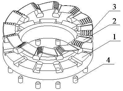
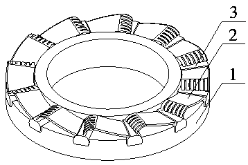
[0026] refer to Figure 1-Figure 8 As shown, the present invention is a foil end surface gas film sealing structure with enhanced radial flow-induced opening, including a gas film-sealed moving ring and a static ring; it is characterized in that:

[0027] At least one sealing ring in the moving ring or static ring is a floating ring supported by a spring, the sealing end face of the floating ring is a foil end face, one side of the foil end face is the high pressure side, and the foil end face The other side is the low pressure side;

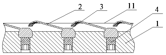
[0028] The end surface of the foil includes a ring-shaped ring body 1, foil 2, foil fixing seat 3, and set screw 4; the outer side of the ring body 1 is lowered to form a circular concave surface, and the inner side of the ring body is raised, An annular step is formed, the upper surface of the annular step ...


PUM


Abstract

The invention discloses a foil end face gas film sealing structure with enhanced radial flow-induced opening. The structure comprises a moving ring and a static ring which are sealed by a gas film, atleast one sealing ring of the moving ring or the static ring is a floating ring supported by a spring, and the sealing end of the floating ring is a foil end face; the foil end face comprises a ring-shaped ring body, a foil, a foil fixing seat and a fastening screw; a plurality of positioning grooves are uniformly formed in the circumferential direction of the ring body; part of the foil is bentto form a bent foil, the other part of the foil is flat and straight to form a straight foil, the bent foil is cut into small pieces in the radial direction, and the cross section of the straight foilin any radial direction is a wing-shaped cross section; the foil fixing seat is inserted into a positioning groove through clearance fit to be fixed through the fastening screw; the end, away from the foil, of the straight foil is welded to the foil fixing seat; the circumferential direction of the part from the flat and straight end to the bent end of the foil is conformed to the circumferentialdirection of air flow.

Description

technical field [0001] The invention relates to the technical field of mechanical end face sealing structure design, in particular to a foil end face air film sealing structure with enhanced opening due to radial flow, and is especially suitable for shaft end sealing devices of various high-speed rotating machines. Background technique [0002] The end face gas film seal, also known as the dry gas seal, is a non-contact mechanical seal with gas as the sealing medium. The end face seal is realized by pressing a pair of rigid sealing rings. It was first introduced by Jones Crane Sealing Company in the 1960s. propose. Due to the advantages of low leakage, long life, low power consumption, etc., the dry gas seal was widely used in high-speed rotating machinery, such as high-speed centrifugal compressors and centrifugal pumps, shortly after it was proposed. However, the current working conditions of rotating machinery are generally developing towards high parameters (high speed,...

Claims


Application Information

Patent Timeline
Patent Type & Authority Applications(China)
IPC IPC(8): F16J15/34
CPCF16J15/3464
Inventor 陈源彭旭东江锦波严天宏李孝禄张远辉
Owner CHINA JILIANG UNIV
Why Eureka
Try Eureka