
Reverse air jetting air bubble assisting high-speed water inlet reducing impact load mechanism
A technology of impact load and cavitation, which is applied in the field of high-speed entry of moving objects into water, can solve the problem of large area of the navigating body, and achieve the effect of being conducive to stability.
- Summary
- Abstract
- Description
- Claims
- Application Information
AI Technical Summary
Problems solved by technology
Method used
Image

Examples
Embodiment Construction
[0010] The present invention will be further described below in conjunction with the accompanying drawings.
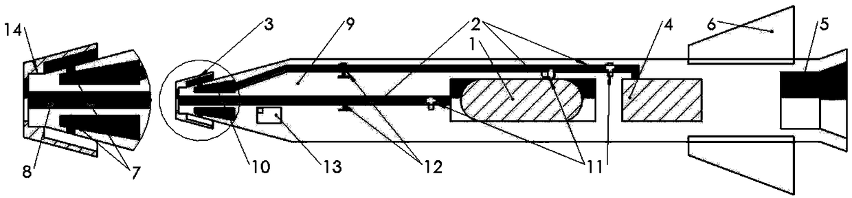
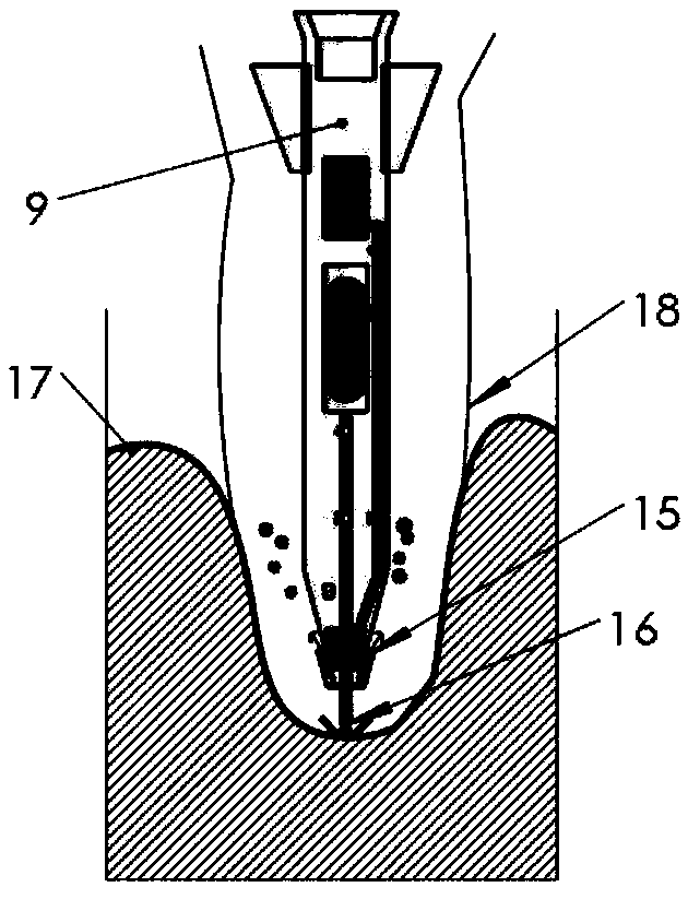
[0011] as attached figure 1 Shown, is the schematic diagram of mechanism of the present invention; Comprising high-pressure gas bottle 1, gas circuit 2, fairing 3, engine 4, nozzle 5, empennage 6, air hole 7, high-speed gas jet hole 8, moving body 9, air cavity 10, electronic pressure regulating valve 11, electronic flow meter 12, computer control device 13, threaded connection device 14; Fairing cover 3 is connected on moving body 9 head by thread 14, and some air holes 7 are evenly distributed in the circumferential direction of moving body head, and air hole and The annular air cavity 10 inside the shell is connected, and the engine supplies air to the air cavity through the air circuit 2. The electronic pressure regulating valve 11 and the electronic flow meter 112 are arranged on the air circuit, and the air cavity is connected to the high-speed gas jet hole 8 on ...
PUM
 Abstract
Description
Claims
Application Information