Floating ball machine structure

A float machine and ball hole technology, applied in sports accessories, indoor games, etc., can solve problems that are difficult to be called practical, inconvenient for players to use, and players cannot play other games

Inactive Publication Date: 2019-05-17
BINGOTIMES DIGITAL TECH
View PDF15 Cites 0 Cited by
  • Summary
  • Abstract
  • Description
  • Claims
  • Application Information

AI Technical Summary

Problems solved by technology

Although the purpose of the ball-drawing game 1 can be obtained above, there are the following disadvantages: the ball-drawing game machine 10 can only perform one game of ball-drawing 1 at the same time, and the player cannot play other games, and can only wait for the game to end. It is inconvenient for players to leave and look for other game machines. If multiple game machines are used to play games at the same time, it is difficult for players to observe and understand the balls drawn by each game in progress. As far as dealers are concerned, the use of the ball-drawing game machine 10 is limited and cannot achieve better economic efficiency, so it is difficult to be called practical

Method used


Image

  • Floating ball machine structure
  • Floating ball machine structure
  • Floating ball machine structure

Examples


Embodiment Construction

[0070] The present invention will be further described below in conjunction with the accompanying drawings and specific embodiments, so that those skilled in the art can better understand the present invention and implement it, but the examples given are not intended to limit the present invention.

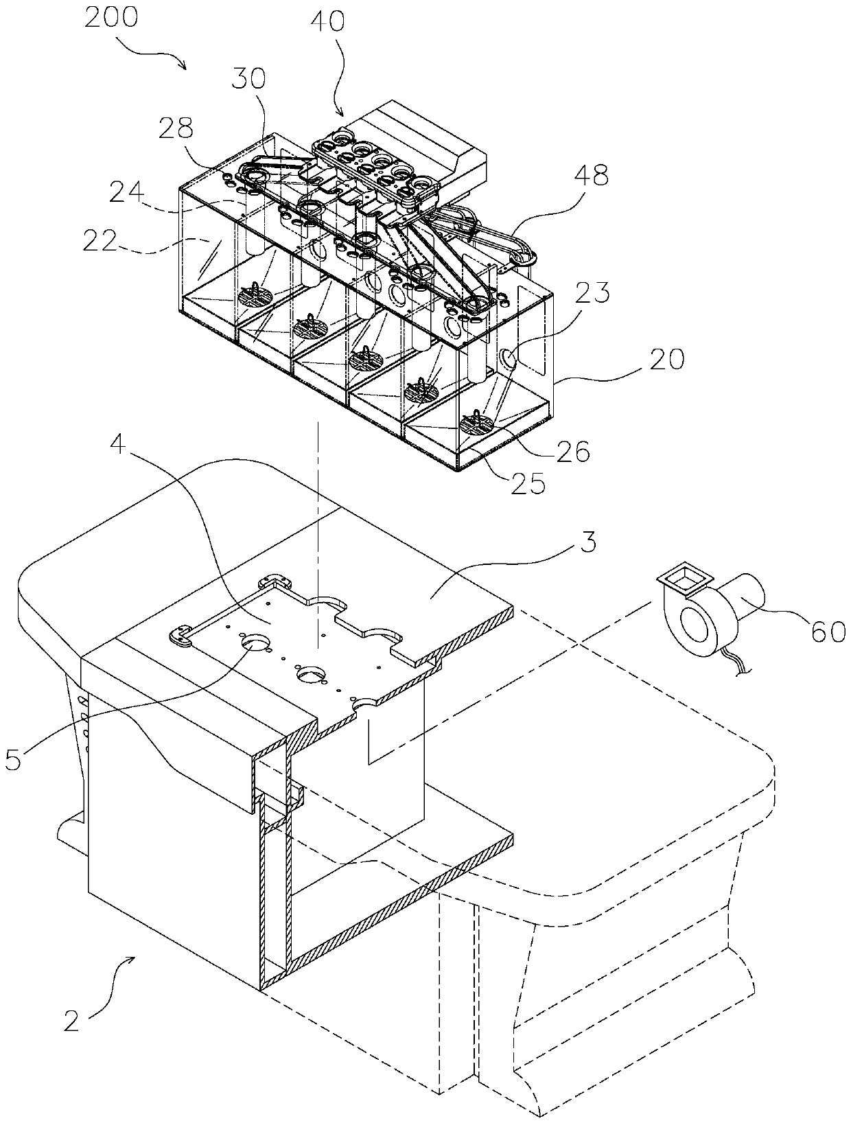
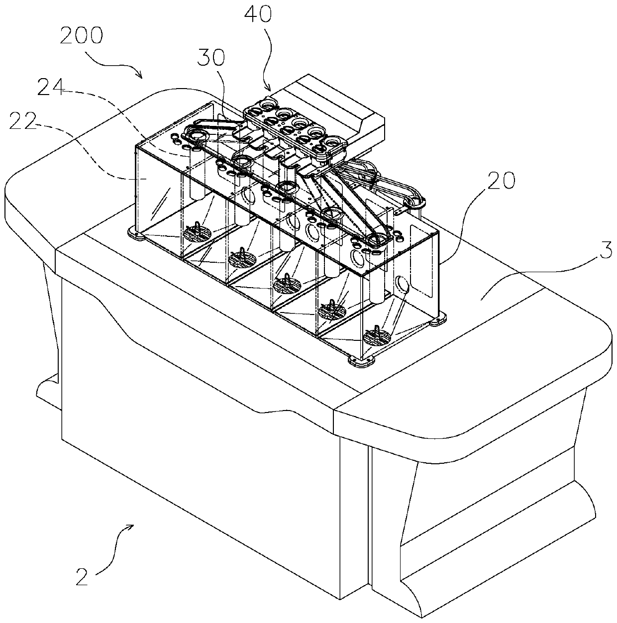
[0071] see Figure 2 to Figure 16 Shown, the structure of a kind of floating ball machine comprises: a box body 20, is the rectangular box with open bottom, and this box body 20 is provided with a plurality of identical dividing plates 21, makes it be divided into a plurality of ball setting spaces 22, The rear side of the ball space 22 is respectively provided with a goal opening 23, the top of the ball space 22 wears a ball-getting pipe 24 respectively, and a ball tray 25 is respectively set below the ball space 22, and a ball tray 25 is arranged in the center of the ball tray 25. Air outlet 26, this air outlet 26 is corresponding to the position below this ball pipe 24, and thi...


PUM


Abstract

The invention provides a floating ball machine structure which comprises a box body, a ball guide seat and a ball control seat, wherein the box body is provided with multiple ball storage spaces; a ball taking tube penetrates through the top of the box body; a ball disc is arranged below the box body; the ball guide seat is provided with a top plate and a seat body; a plurality of upper through holes and a ball return hole are formed in the plate surface of the top plate; a plurality of ball grooves are formed inside the seat body; the upper ends of the ball grooves are connected with the upper through holes; the lower ends of the ball grooves are communicated with the ball taking tube; the ball control seat comprises an upper seat plate component, a lower seat plate, at least two verticalplates, multiple containing tubes, multiple displacement plates, multiple ball tracks and multiple air blower components; the upper seat plate component is provided with multiple ball outlet holes; acrosspiece is arranged in the ball outlet holes; the lower seat plate is assembled above the top plate of the ball guide seat and provided with multiple limiting holes; the at least two vertical plates are arranged between the upper seat plate component and the lower seat plate to form an overhead space; the multiple air blower components are arranged below the ball disc. According to the structure, different games can be played by the same machine at the same time, so that the interestingness of players is improved, and economic benefits of game consoles are increased.

Description

technical field [0001] The invention relates to a structure of a floating ball machine, in particular to a recovery path that can coordinate with various computer games to draw balls and switch different balls at the same time. Background technique [0002] The current common ball game machines, please refer to figure 1 As shown, it includes: a circular cylinder 11 with a ball-taking tube 12 pierced therein; a ball track 13 with an upper opening 131 and a lower opening 132, and the upper opening 131 is socketed with the ball-taking tube 12; a ball The road control mechanism 14 includes a box body 141, a guide groove 15 and a recovery box 16, the box body 141 can swing, and is provided with a ball entering hole 142 and a ball returning hole 143 corresponding to the lower opening 132 respectively; With the above structure, a plurality of balls 1 can be placed in the barrel 11 in a "blowing and floating" manner, and one of the balls 1 can be drawn out at a time, and the ball p...

Claims


Application Information

Patent Timeline
Patent Type & Authority Applications(China)
IPC IPC(8): A63F7/00A63F7/36
Inventor 罗志宗
Owner BINGOTIMES DIGITAL TECH
Why Eureka
Try Eureka