

Household appliance
A technology for household appliances and controllers, which is applied to household stoves, household heating, household appliances, etc., can solve the problems of complex process, unfavorable use by users, and long waiting time for users, and achieve the effect of quick disassembly and assembly.
- Summary
- Abstract
- Description
- Claims
- Application Information
AI Technical Summary
Problems solved by technology
Method used
Image

Examples
Embodiment 1
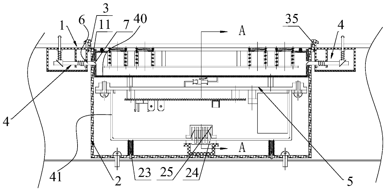
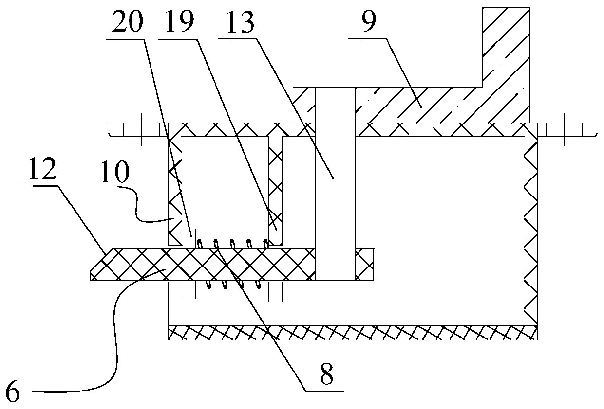
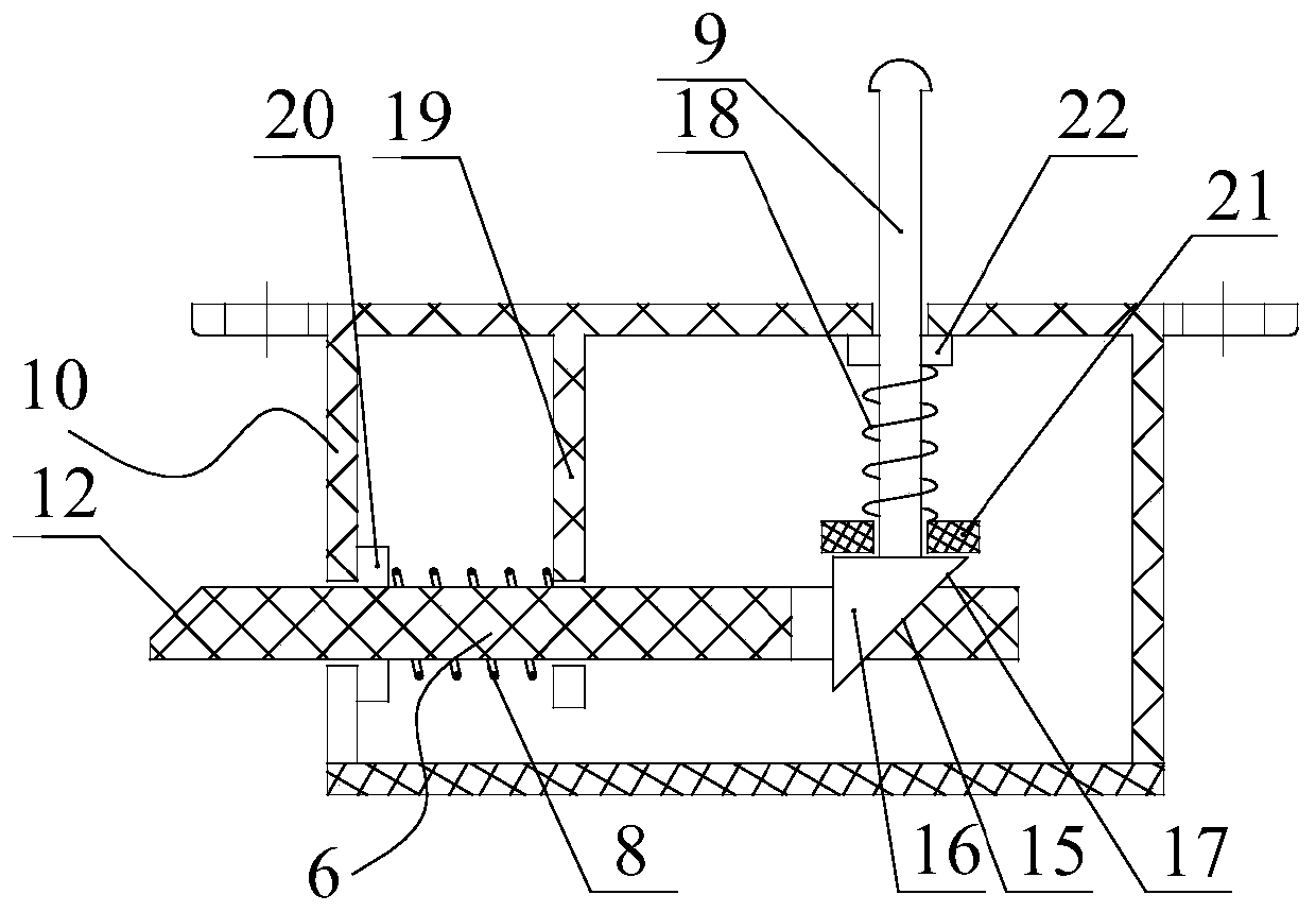
[0062] Such as figure 1 , 2 , 3, 4 and 5, a controller installation structure, including:
[0063] mount 1;
[0064] The installation box 2 has an opening 3, and the installation box 2 is arranged on the installation seat 1;
[0065] The controller 5 is detachably installed in the installation box 2 through the opening 3;
[0066] The locking mechanism 4 is arranged on the installation seat 1, the installation box 2 or the controller 5. The locking mechanism 4 has a movable locking member 6, and the locking or unlocking of the controller 5 is realized by the movement of the locking member 6. 5. When the controller 5 is in the locked state, the locking member 6 fixes the controller 5 relative to the installation box 2 or the installation base 1 .
[0067] The mounting base 1 of the present application may be a panel or a side wall of an electrical appliance, and one of its main functions is to carry the controller 5 . The installation box 2 mentioned in this application is...
Embodiment 2
[0099] Such as Figure 13 and 14 As shown, a household appliance includes the installation structure of the controller of Embodiment 1, and also includes a control knob 38 detachably installed on the mounting base 1 (that is, the household appliance in this embodiment is a household appliance with a control knob), and the control The knob 38 includes a knob body 39 , and the first unlocking member 9 of the locking mechanism 4 is disposed directly below the knob body 39 . Setting the first unlocking part 9 directly below the knob body 39 can hide the first unlocking part 9 through the knob body 39, effectively preventing accidental touches. When the first unlocking part 9 needs to be controlled, only the control knob 38 needs to be removed. When the first unlocking part 9 is exposed, it is convenient for the user to control.
[0100] Preferably, the locking mechanism 4 of the present embodiment adopts image 3 and Figure 4 These two structures, because one end of the first...
PUM
 Abstract
Description
Claims
Application Information