Rear tire unloading device of tire vulcanizer

A tire vulcanization and frame technology, which is applied to tires, other household appliances, household appliances, etc., can solve the problems of low efficiency of vulcanizing machines, affecting the service life of the bladder, and the inability of the bladder to stretch, etc., to achieve simple structure, convenient control, The effect of short unloading time

Pending Publication Date: 2019-10-25
GUILIN RUBBER MACHINERY CO LTD
View PDF0 Cites 0 Cited by
  • Summary
  • Abstract
  • Description
  • Claims
  • Application Information

AI Technical Summary

Problems solved by technology

[0002] At present, the conventional single-mode tire shaping vulcanizer uses a manipulator to unload the tire from the front. Since the manipulator can both load and unload the tire, the non-vulcanization time is long and the use efficiency of the vulcanizer is low; Synchronous flipping, or the tire unloading mechanism goes in from the back of the vulcanizing machine to unload the tire. This mechanism not only results in a longer non-vulcanizing time, but also cannot be lifted and turned, causing the bladder to be unable to stretch and affect the service life of the bladder.

Method used


Image

  • Rear tire unloading device of tire vulcanizer
  • Rear tire unloading device of tire vulcanizer
  • Rear tire unloading device of tire vulcanizer

Examples


Embodiment Construction

[0016] The technical solutions of the present invention will be further described below in conjunction with the embodiments shown in the accompanying drawings.

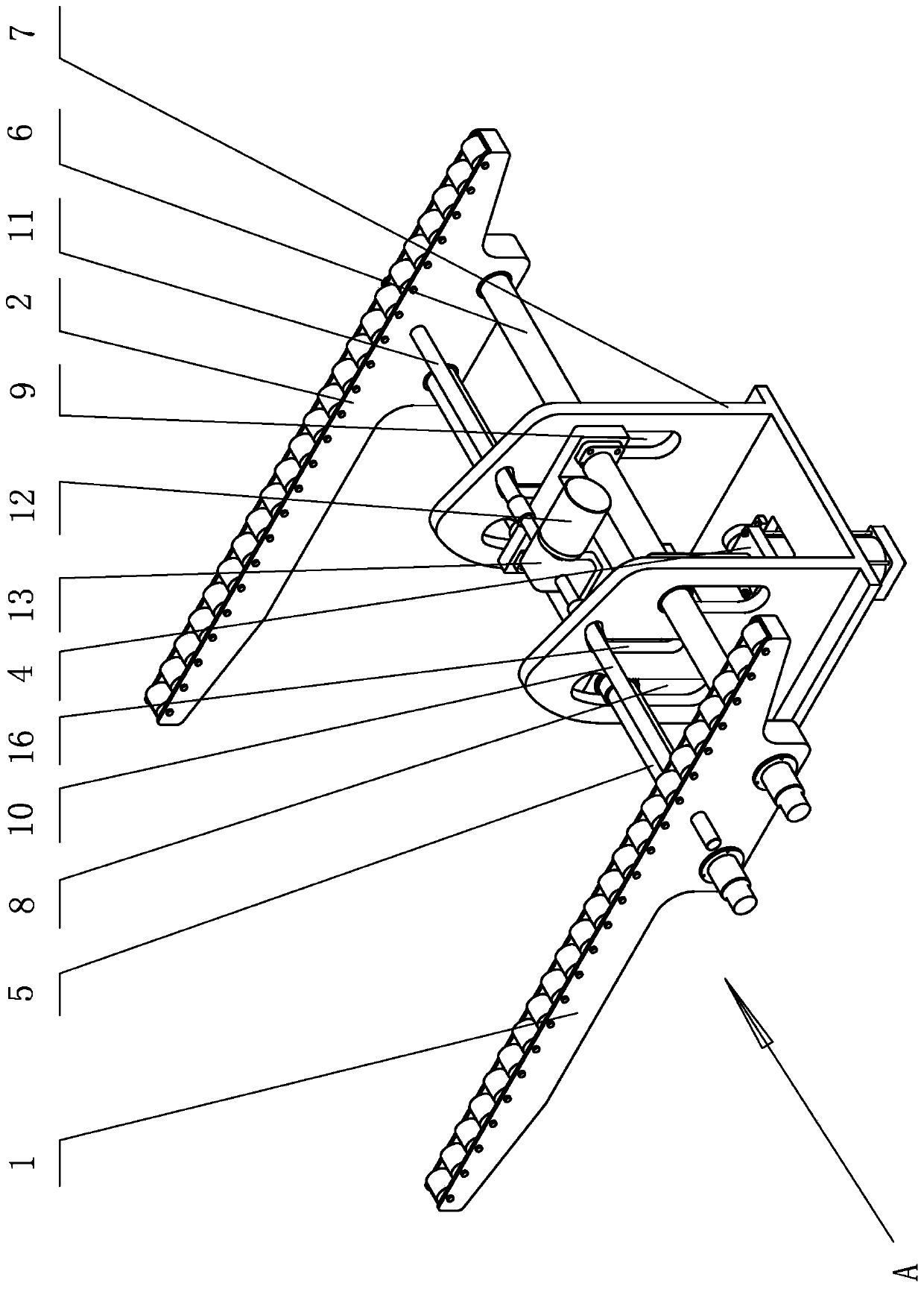
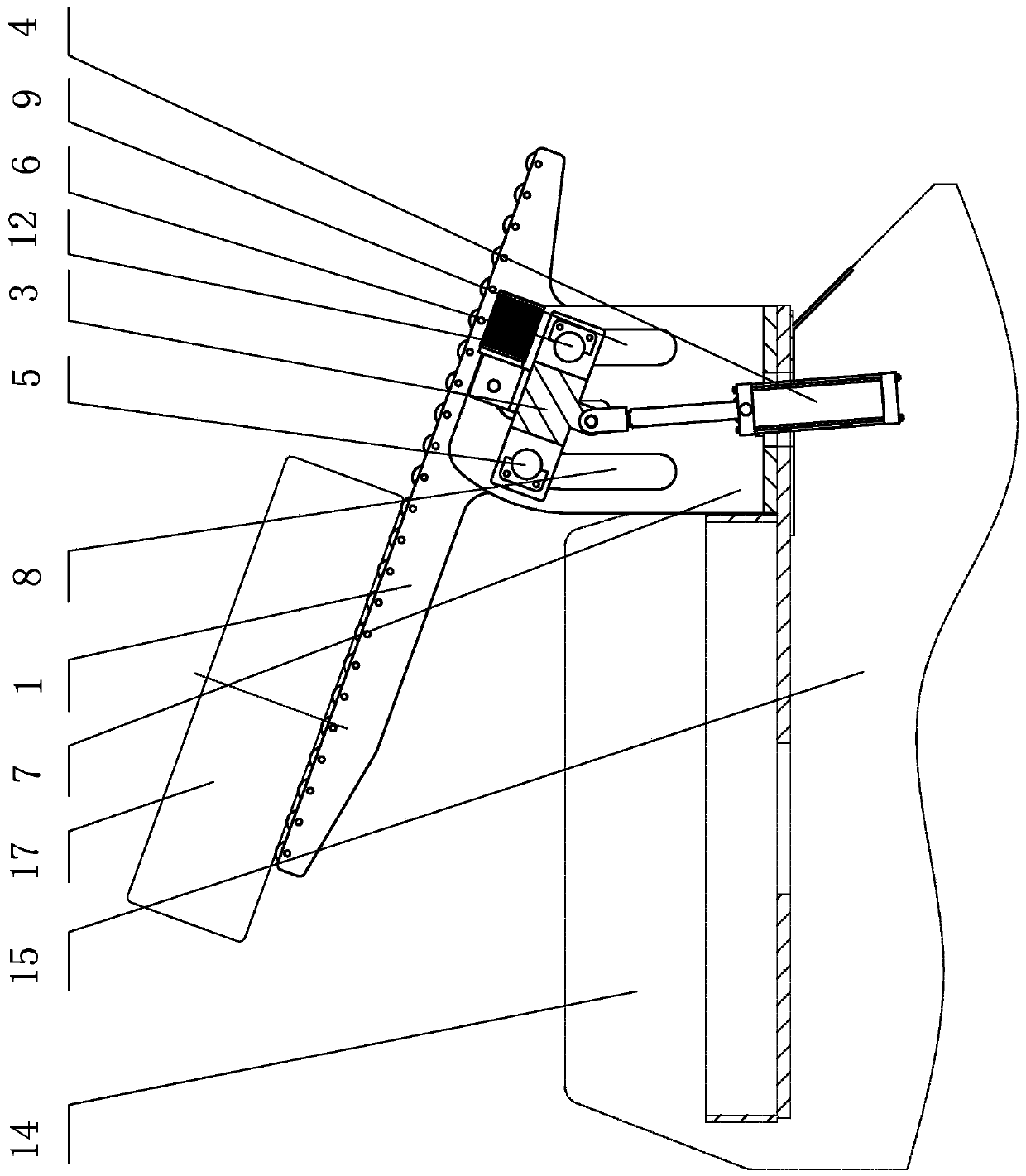
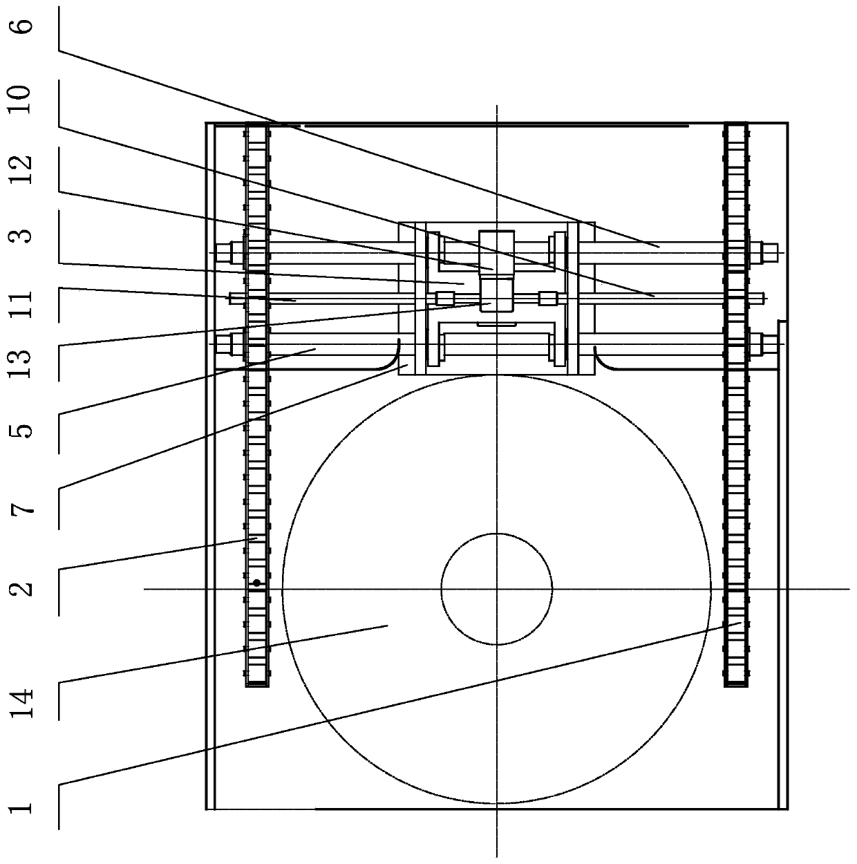
[0017] The rear tire unloading device of the tire curing machine of the present invention includes a left and right synchronous opening and closing mechanism, a lifting and turning mechanism, and left and right tire unloading arms 1 and 2 provided on the basis of the tire unloading frame 7, and the tire unloading frame 7 is installed in the vulcanization chamber On the rear support 15 of 14, unloading tire frame 7 comprises base plate (being installed on the support 15) and the left and right side plates of base plate both sides, as figure 1 , figure 2 , image 3 shown.

[0018] The lifting and turning mechanism includes a lifting frame 3 and a lifting hydraulic cylinder 4 (preferably a water cylinder), and the lifting frame 3 is placed in the left and right side panels of the tire unloading frame 7. The bottom an...


PUM


Abstract

The invention discloses a rear tire unloading device of a tire vulcanizer. The rear tire unloading device is characterized in that a left tire unloading arm and a right tire unloading arm are mountedon a lifting and turning mechanism through a left-right synchronous opening and closing mechanism; the lifting and turning mechanism comprises a lifting frame and a lifting hydraulic cylinder; front guiding shafts and rear guiding shafts are respectively mounted at the front and rear ends of the lifting frame, and arranged in front guiding shaft sliding grooves and rear guiding shaft sliding grooves; the front guiding shaft sliding grooves and the rear guiding shaft sliding grooves are vertically formed in the left and right sides of a tire unloading rack; the top of each front guiding shaft sliding groove is designed to be a circular-arc groove higher than the top of the corresponding rear guiding shaft sliding groove; the left tire unloading arm and the right tire unloading arm are slidably mounted at the left and right ends of the front guiding shafts and the rear guiding shafts; the cylinder body of the lifting hydraulic cylinder is mounted on the position, below the lifting frame,of the tire unloading rack in a hinging manner; a hydraulic rod of the lifting hydraulic cylinder is upwardly mounted at the bottom of the lifting frame in a hinging manner; and the lifting frame islifted by the hydraulic rod and backward turned with the tops of the rear guiding shaft sliding grooves as the circle center and with the circular-arc sections of the front guiding shaft sliding grooves as the radius. The rear tire unloading device disclosed by the invention has the beneficial effects that the tire unloading time is short; the efficiency of the tire vulcanizer is high; the structure is simple; the control is convenient; and the manufacturing cost and the use cost are low.

Description

technical field [0001] The invention relates to a component structure of a tire vulcanizing machine, in particular to a rear tire unloading device of a tire vulcanizing machine. Background technique [0002] At present, the conventional single-mode tire shaping vulcanizer uses a manipulator to unload the tire from the front. Since the manipulator can both load and unload the tire, the non-vulcanization time is long and the use efficiency of the vulcanizer is low; Synchronous flipping, or the tire unloading mechanism goes in from the back of the vulcanizing machine to unload the tire. This mechanism not only causes a long non-vulcanization time, but also cannot be lifted and turned, causing the bladder to be unable to stretch, which affects the service life of the bladder. Contents of the invention [0003] Aiming at the deficiencies of the prior art, the technical problem to be solved by the present invention is to propose a rear tire unloading device for a tire vulcanizer...

Claims


Application Information

Patent Timeline
Patent Type & Authority Applications(China)
IPC IPC(8): B29C35/02B29L30/00
CPCB29C35/02B29L2030/00
Inventor 张红飞邓永松韦金桂熊礼云周艳玲
Owner GUILIN RUBBER MACHINERY CO LTD
Why Eureka
Try Eureka