Positioning Mechanism for Folding and Assembling the Gear Shaft Used in Gear Pump

A technology of positioning mechanism and gear pump, which is applied in the direction of workpiece clamping devices, manufacturing tools, hand-held tools, etc., can solve the problems of lack of positioning mechanism, large noise, and offset of gear shafts, and achieve improved assembly quality and accuracy Effect

Active Publication Date: 2020-11-20
台州蓝天企业服务有限公司
View PDF4 Cites 0 Cited by
  • Summary
  • Abstract
  • Description
  • Claims
  • Application Information

AI Technical Summary

Problems solved by technology

[0005] In order to solve the above-mentioned technical problems, the present invention provides a positioning mechanism when the gear shaft of the gear pump is folded to solve the problem that the existing gear pump described above lacks a reasonable positioning mechanism when the gear shaft is installed, resulting in inaccurate installation and positioning of the gear shaft , especially when the internal gear shafts of some gear pumps with electronic carbon brushes at both ends are installed, unlike the gear pumps with bearing-type fixed structures at both ends, the gear shafts are fixed by bearings, and the carbon brushes The type of gear pump adopts carbon brushes to be directly buckled on both sides of the gear shaft. Since the carbon brushes at both ends of this gear pump are elastic and flexible, if the gear shaft is installed, there is no reasonable positioning mechanism at both ends, which will eventually cause After the gear shaft is fixed in the pump chamber, it will deviate, which will affect the normal rotation action, or generate a lot of noise during the rotation process.

Method used


Image

  • Positioning Mechanism for Folding and Assembling the Gear Shaft Used in Gear Pump
  • Positioning Mechanism for Folding and Assembling the Gear Shaft Used in Gear Pump
  • Positioning Mechanism for Folding and Assembling the Gear Shaft Used in Gear Pump

Examples


Embodiment

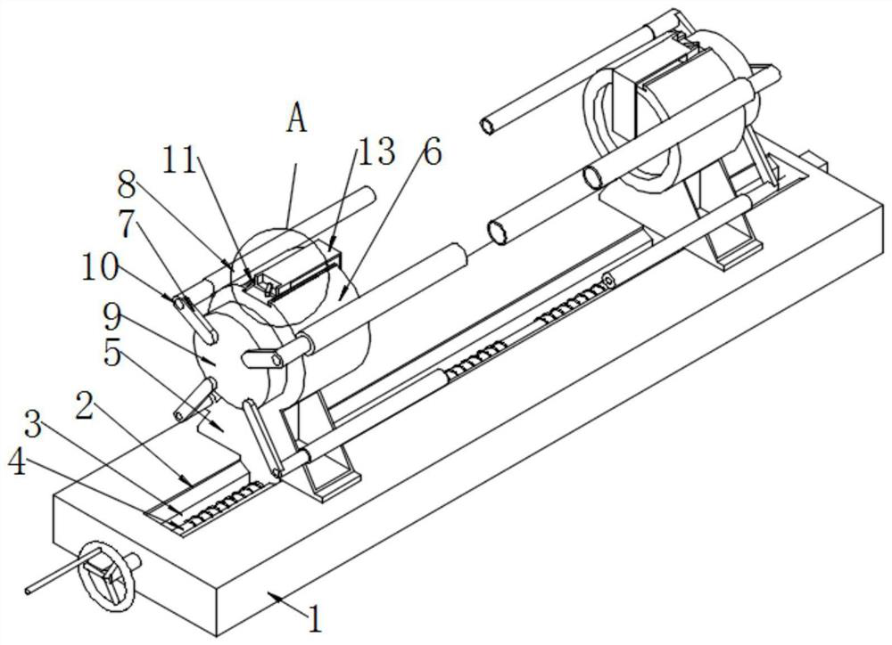
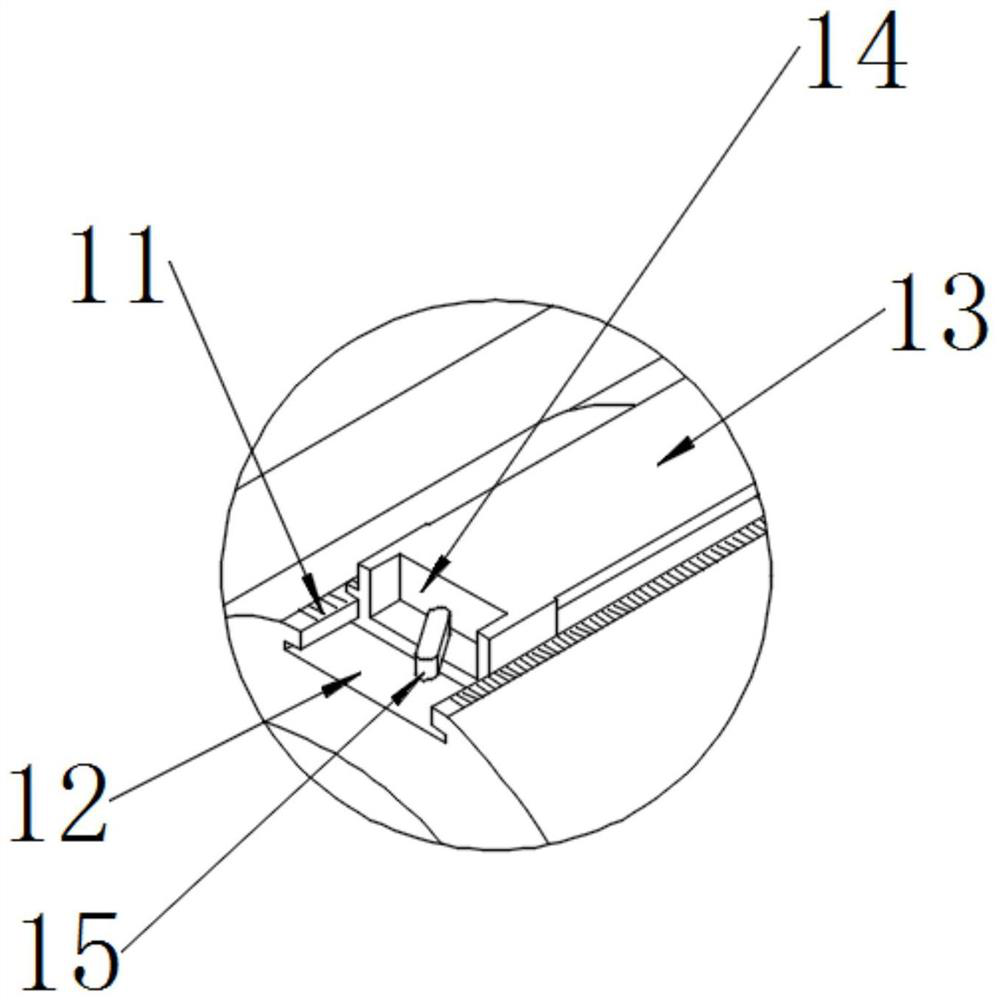
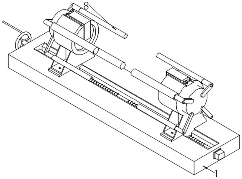
[0032] as attached figure 1 to attach Figure 9 Shown:

[0033] The present invention provides a positioning mechanism for gear pumps when the gear shaft is folded and assembled, including a base 1; the base 1 is a rectangular plate base structure, and a slideway 2 with a rectangular notch structure is provided in the middle of the plate base, and the slideway In 2, a double-headed reverse lead screw 4 is installed by means of rotation and coordination, which constitutes a screw-type transmission mechanism, and the two-way reverse screw can make the mechanism matched on the two-stage screw rods realize opposite and opposite directions. Synchronous moving action in the direction; the middle position of the slideway 2 is provided with a slide rail 3 structure, and through this slide rail 3 structure, there are two slide seats 5 on the left and right, and the bottoms of the two slide seats 5 are also passed through The circular threaded hole fits on the left and right sections ...


PUM


Abstract

The invention provides a positioning mechanism for a gear pump gear shaft when it is folded and assembled, including a base; the base is a rectangular plate base structure, and a slideway with a rectangular notch structure is provided in the middle of the plate base, and the slideway is rotated to fit A double-headed reverse lead screw is installed in the same way; a slide rail structure is provided in the middle of the slideway, and there are two sliding seats on the left and right through this slide rail structure; due to the carbon brush type gear pump magnetic pole The carbon brushes are located on both ends of the cover, so after the two ends of the tube are supported by the pipe fittings, they are on the same axis. At this time, the gear shaft between the two ends of the cover is docked from the middle area of ​​the end cover, and during the docking process, the two The end cover is affected by the sliding seat on both sides to realize synchronous tightening, so that the gear shaft is more reasonably installed on the original magnetic pole carbon brushes inside the left and right end covers, and the internal gear shaft of this carbon brush gear pump is improved. The accuracy after installation improves the assembly quality of the gear pump.

Description

technical field [0001] The invention belongs to the technical field of positioning mechanism structure, and more specifically relates to a positioning mechanism when a gear shaft for a gear pump is folded and assembled. Background technique [0002] The gear pump is a rotary pump that relies on the change and movement of the working volume formed between the pump cylinder and the meshing gear to deliver or pressurize the liquid. Two closed spaces are composed of two gears, the pump body and the front and rear covers. When the gears rotate, the volume of the space on the side where the gears are disengaged increases from small to large, forming a vacuum to suck the liquid, and the volume of the space on the side where the gears mesh changes from large to large. Small, and the liquid is squeezed into the pipeline. The suction chamber and the discharge chamber are separated by the meshing line of two gears. The pressure at the outlet of the gear pump depends entirely on the r...

Claims


Application Information

Patent Timeline
Patent Type & Authority Patents(China)
IPC IPC(8): B25B11/00B25B27/00
CPCB25B11/00B25B27/00
Inventor 韩树杰
Owner 台州蓝天企业服务有限公司
Why Eureka
Try Eureka