A hydraulic torque converter device with comprehensive damping effect
What is AI technical title?
AI technical title is built by PatSnap AI team. It summarizes the technical point description of the patent document.
A technology for torque converter and vibration damping, which is applied in transmission devices, springs/shock absorbers, fluid transmission devices, etc., can solve the problems of inability to change vibration and difficult to reduce flywheel vibration, and achieves strong usability, The effect of reducing torsional vibration and smooth transmission
Active Publication Date: 2021-06-08
JILIN UNIV
View PDF0 Cites 0 Cited by
Summary
Abstract
Description
Claims
Application Information
AI Technical Summary
This helps you quickly interpret patents by identifying the three key elements:
Problems solved by technology
Method used
Benefits of technology
Problems solved by technology
[0004] Due to the different installation positions of these two damping devices, the final damping effect will be different. The traditional torsional damper is installed after the engine crankshaft and before the flywheel disc. This damping method will only To reduce part of the vibration from the engine crankshaft, the vibration after the flywheel is difficult to reduce. Using a hydraulic torque converter for vibration reduction can reduce the vibration before the flywheel of the engine, but it cannot change the vibration caused by irregular loads
Method used
Image
Click on the blue label to locate the original text in one second.
Reading with bidirectional positioning of images and text.
Examples
Embodiment Construction
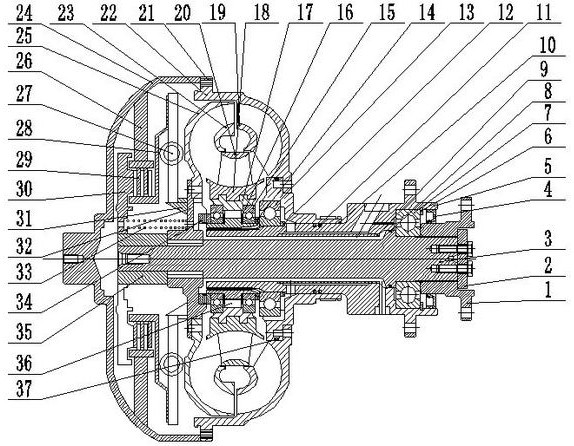
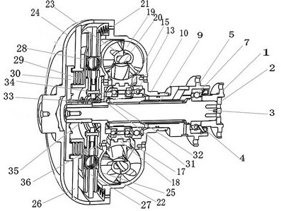
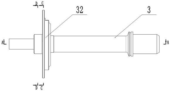
[0040] see Figure 1 to Figure 9 As shown, a hydraulic torque converter device with comprehensive damping effect includes right cover plate 1, pressure plate 2, turbine output shaft 3, seal ring 4, flange plate 5, right bearing 7, turbine output Shaft length sleeve 9, pump wheel bearing support seat 10, pump wheel bearing 13, guide wheel bearing 15, guide wheel support seat 17, guide wheel hub 18, pump wheel inner ring 19, guide wheel inner ring 20, rubber gear 21, Pump wheel casing 22, turbine inner ring 23, pump wheel cover 24, turbine casing 25, support plate 26, torsional shock absorber 27, clutch driven disc 28, clutch driving disc 29, piston 30, turbine flange 31, turbine hub 32. The return spring 33, the left positioning short sleeve 34 of the guide wheel support seat, the short sleeve 35 of the turbine output shaft and the bearing positioning sleeve 36 of the guide wheel support seat, and the right cover plate 1 is set on the turbine output shaft 3, The pressure plate...
PUM
Abstract
The invention discloses a hydraulic torque converter device with comprehensive damping effect, which comprises a right cover plate, a pressure plate, a turbine output shaft, a sealing ring, a flange, a right bearing, a long sleeve of the turbine output shaft, Pump wheel bearing support seat, pump wheel bearing, guide wheel bearing, guide wheel support seat, guide wheel hub, pump wheel inner ring, guide wheel inner ring, rubber gear, pump wheel casing, turbine inner ring, pump wheel cover, turbine casing . Wheel support seat bearing positioning sleeve, the present invention can realize the effect of reducing the torsional vibration of the system under the low-speed working condition, the transitional working condition from the low-speed working condition to the high-speed working condition, and the high-speed working condition, and can reduce the torsional vibration to the greatest extent The torsional vibration of the system achieves the purpose of stable transmission and uniform load.
Description
technical field [0001] The invention relates to the technical field of hydraulic transmission, in particular to a hydraulic torque converter device with comprehensive damping effect. Background technique [0002] As a power source, the engine is also a vibration source. The vibration comes from the reciprocating work between the engine piston and the oil cylinder. The normal operating speed of the engine is as high as 2000rpm, and the oil cylinder will undergo hundreds of times of intake-compression-work - Exhaust process, which will lead to irregular torque output at crankshaft speed, and irregular vibration generated by the engine will exist in the entire transmission system, which will lead to fracture of the transmission shaft in severe cases. [0003] The usual way to solve the irregular vibration of the engine is to use a torsional shock absorber. The torsional shock absorber can store the irregular excitation of the engine through the torsion spring and then release i...
Claims
Application Information
Patent Timeline
Application Date:The date an application was filed.
Publication Date:The date a patent or application was officially published.
First Publication Date:The earliest publication date of a patent with the same application number.
Issue Date:Publication date of the patent grant document.
PCT Entry Date:The Entry date of PCT National Phase.
Estimated Expiry Date:The statutory expiry date of a patent right according to the Patent Law, and it is the longest term of protection that the patent right can achieve without the termination of the patent right due to other reasons(Term extension factor has been taken into account ).
Invalid Date:Actual expiry date is based on effective date or publication date of legal transaction data of invalid patent.

