
Walking toy
A technology for toys and connecting sleeves, which can be used in toys, automatic toys, entertainment, etc., can solve the problem of laborious operation and achieve the effect of simple operation.
- Summary
- Abstract
- Description
- Claims
- Application Information
AI Technical Summary
Problems solved by technology
Method used
Image

Examples
Embodiment 1
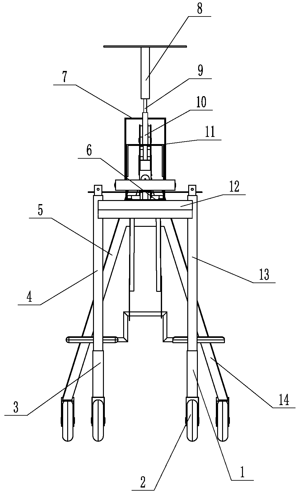
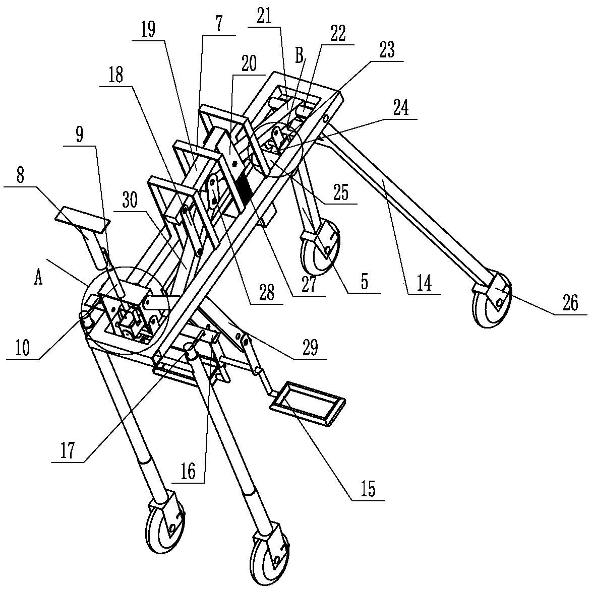
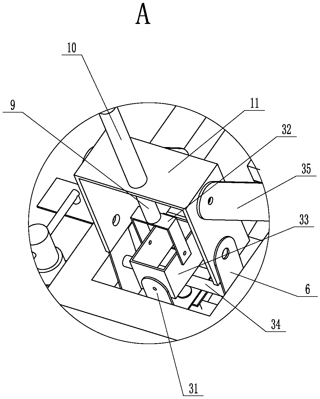
[0031] like Figure 1~12 The shown walking toy includes leg one 14, leg two 5, leg three 1 and leg four 3 and a support frame 40 arranged horizontally, the lower ends of leg one 14, leg two 5, leg three 1 and leg four 3 The caster 2 is connected with the wheel frame 26 respectively, and the caster 2 is connected with the wheel frame 26 through the wheel shaft 42 in rotation. Rotatably connected to the rear portion of the support frame 40, the outside of the leg three 1 is connected with a connection sleeve one 13, the outside of the leg four 3 is connected with a connection sleeve two 4, and the connection sleeve one 13 and the connection sleeve two 4 are fixedly connected with Crossbeam 12, the upper side of crossbeam 12 is fixedly connected with support plate 6 extending upwards outside the support frame 40, and the left and right ends of support plate 6 are hinged with bending plate 11, and support frame 40 is fixedly connected with two connecting rods 35 , the connecting ...
Embodiment 2
[0040] like Figure 13 As shown, the difference from Embodiment 1 is that the folding arm 9 is fixedly connected to the support sleeve 10 , and the angle adjustment plate 31 is fixedly connected to the support plate 6 .
PUM
 Abstract
Description
Claims
Application Information