Cupping jar capable of adjusting pressure

An adjustable pressure and cupping technology, which is applied in the field of medical devices, can solve the problems of tearing and pain on the body surface, increasing the pain of patients, and not being able to achieve the best therapeutic effect.

Inactive Publication Date: 2020-06-19
潘爱平
View PDF0 Cites 0 Cited by
  • Summary
  • Abstract
  • Description
  • Claims
  • Application Information

AI Technical Summary

Problems solved by technology

[0004] However, due to the different operators, it is not easy to grasp the negative pressure value in the tank for this kind of structure. Excessive negative pressure may cause damage to the skin, increase the pain of the patient, and even produce tension blisters, while the negative pressure value is too small to treat And the effect is not good
Moreover, for different patients and different conditions, different negative pressure values ​​should be used to achieve good therapeutic effects. The negative pressure value in the existing cupping tank cannot be standardized and controlled, so the best therapeutic effect cannot be achieved.
In addition, the air valve of the existing manual vacuum cupping is at the top, which is often encountered when covering clothes, which can easily lead to gas leakage
In addition, when the cupping jar is removed from the body surface, due to the negative pressure inside the cupping jar, it will cause tearing and pain on the body surface

Method used


Image

  • Cupping jar capable of adjusting pressure
  • Cupping jar capable of adjusting pressure
  • Cupping jar capable of adjusting pressure

Examples


Embodiment 1

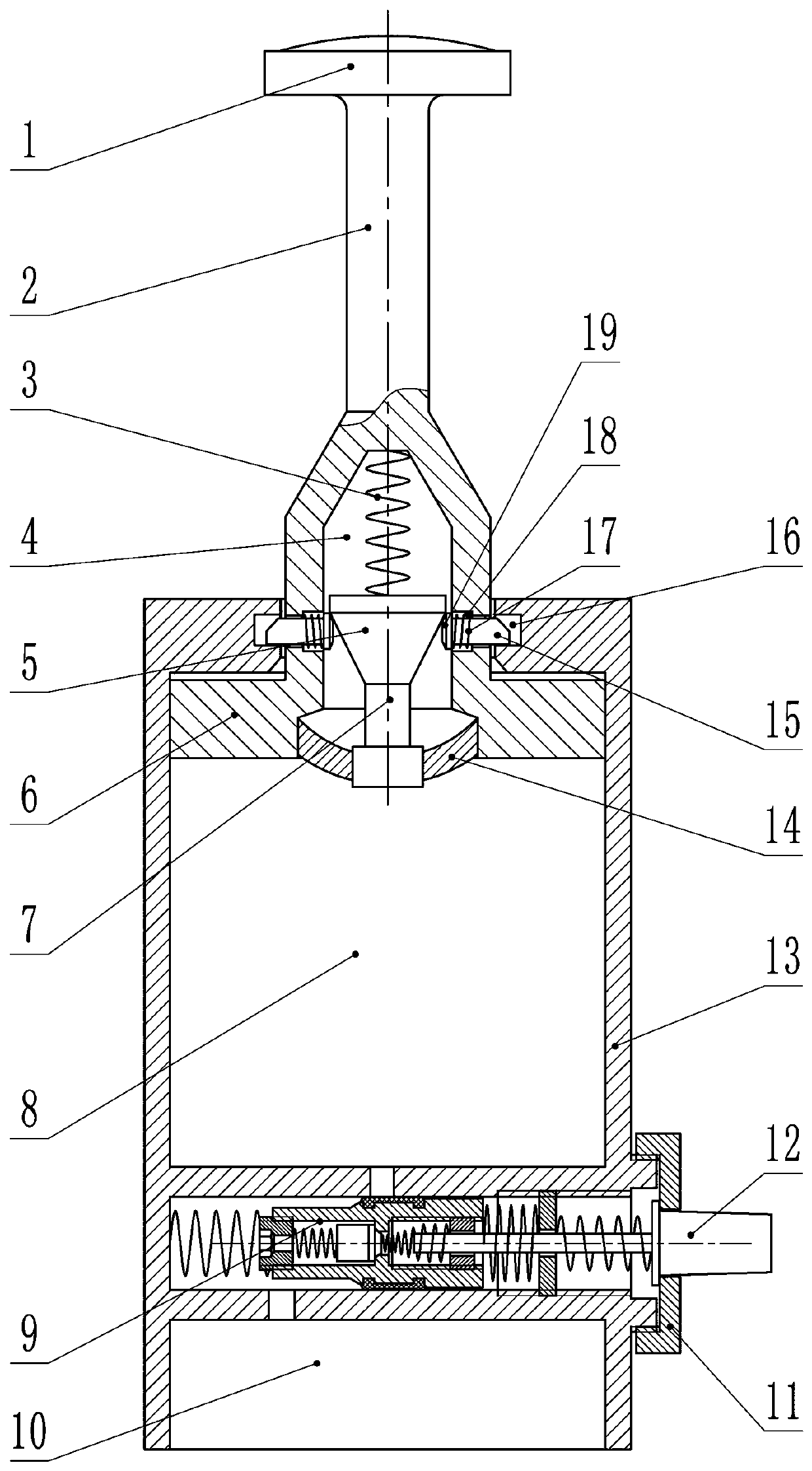
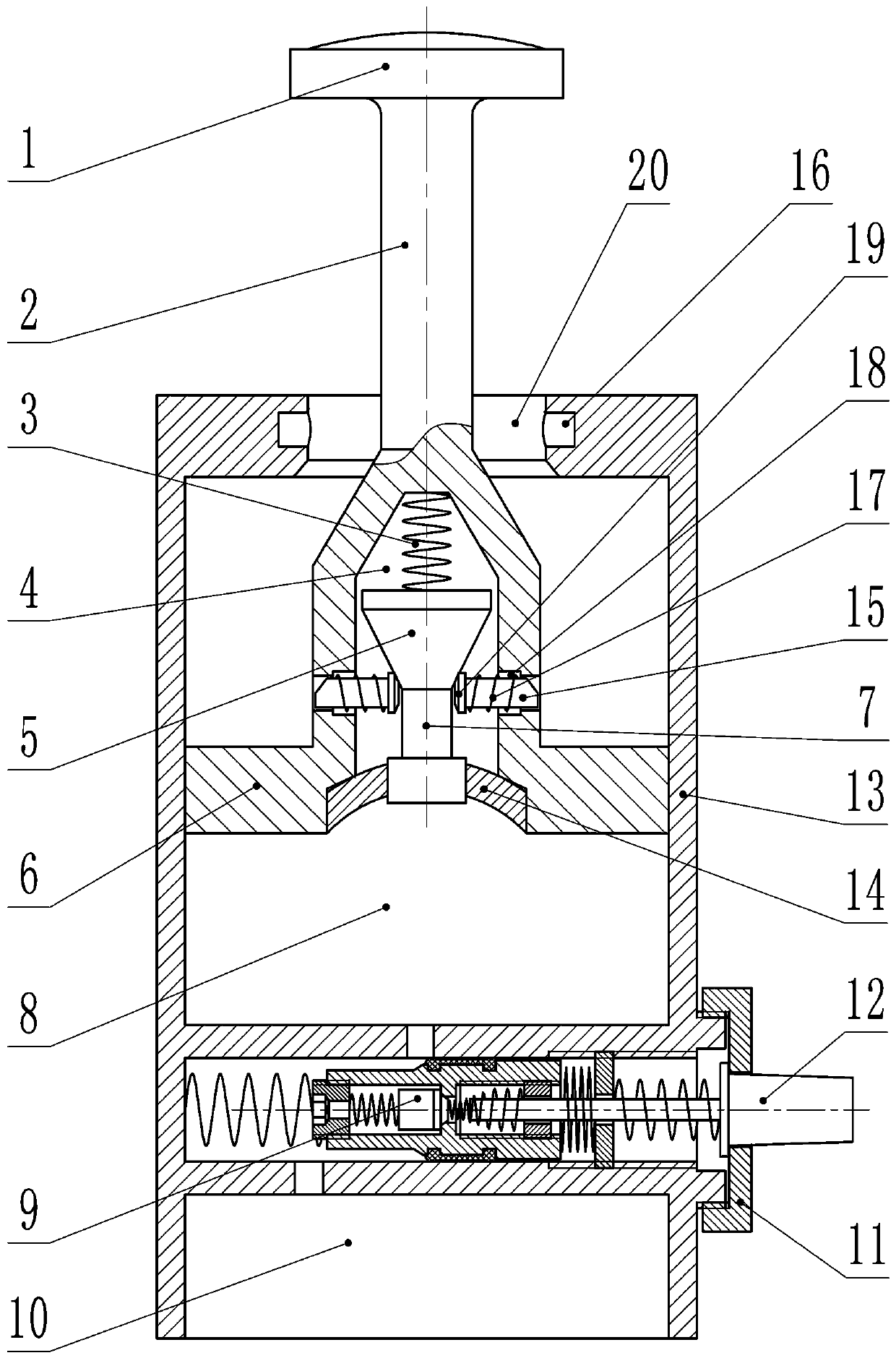
[0019] In embodiment 1, such as figure 1 , 2 , 3, the present embodiment includes a tank body 13, a valve body 9, a piston 6 and a piston rod 2. The tank body 13 is a cylinder structure with an open lower end, the valve body 9 is located in the middle of the tank body 13, and the tank body 13 is divided into two cavities, an upper chamber 8 and a lower chamber 10, by the structure of the valve body 9 . The piston 6 is located in the upper chamber 8, the periphery of the piston 6 is airtightly connected with the inner surface of the tank body 13, the piston 6 is fixedly provided with a piston rod 2, the upper wall of the tank body 13 is provided with a piston hole 20, and the piston rod 2 passes through Through the piston hole 20, the upper end of the piston rod 2 is exposed from the tank body 13, and the upper end of the piston rod 2 is provided with a piston handle 1, which can pull the piston 6 to move up and down through the action of the piston handle 1, and the upper ch...

Embodiment 2

[0030] In embodiment 2, such as Figure 4 As shown, this embodiment includes a tank body 13, a valve body 9, a piston 6 and a piston rod 2, wherein the structure of the main body of the tank body 13 and the valve body 9 is the same as in Embodiment 1, and the difference between this embodiment and Embodiment 1 is the technical feature As for the structure of the upper wall of the piston 6, the piston rod 2 and the tank body 13, only the distinguishing technical features are described in this embodiment, and the same technical features as those of the first embodiment are not repeated here.

[0031] The lower end of the piston rod 2 is fixed on the piston 6, and the periphery of the piston rod 2 is provided with one or more leaf springs 41, and the upper end of the spring leaf 41 is fixedly connected with the upper end of the piston rod 2. The lower end of the spring leaf 41 is tilted outward. The diameter of the piston hole 20 on the upper wall of the tank body 13 is greater ...

Embodiment 3

[0033] In embodiment 3, such as Figure 5 As shown, this embodiment includes a tank body 13, a valve body 9, a piston 6 and a piston rod 2, wherein the structure of the main body of the tank body 13 and the valve body 9 is the same as in Embodiment 1, and the difference between this embodiment and Embodiment 1 is the technical feature As for the structure of the piston 6, the piston rod 2 and the upper wall of the tank body 13, only the distinguishing technical features will be described in this embodiment, and the same technical features as those in the first embodiment will not be described again.

[0034] Described piston 6 and piston rod 2 lower end axis places are provided with the piston cavity 4 of lower end opening, and piston rod 2 is provided with the second stepped hole 45 that communicates with piston cavity 4 and piston rod 2 outsides, and the second stepped hole 45 The position satisfies that when the piston 6 moves to the uppermost position, the outer end openin...


PUM


Abstract

The invention discloses a cupping jar capable of adjusting pressure, and belongs to the field of medical apparatuses. The cupping jar capable of adjusting pressure is characterized by comprising a jarbody, a valve body, a piston and a piston rod, wherein the valve body is located in the middle position of the jar body; a horizontal hole is formed in the middle of the valve body, and a No. 1 spring, a cylinder, a No. 4 spring, a No. 2 thread barrel and a No. 5 spring are sequentially arranged in the horizontal hole from back to front; a center hole is formed in the axle center of the cylinder,and a No. 2 spring, a No. 1 column body, a No. 3 spring and a No. 1 thread barrel are sequentially arranged in the center hole from back to front; and a knob is arranged in front of the horizontal hole. Compared with the prior art, the cupping jar capable of adjusting pressure disclosed by the invention has the characteristic that the pressure in the cupping jar is constant and adjustable.

Description

technical field [0001] This invention is a divisional application of the invention patent "A Cupping Pot with a Negative Pressure Compensation Chamber" (Application No.: 2018101474183), which relates to a medical device, especially a pressure-adjustable cupping pot. Background technique [0002] Cupping is a common treatment device in traditional Chinese medicine. Its principle is to use methods such as burning fire and pumping air to generate negative pressure, so that it can be adsorbed on the body surface, causing local blood stasis, so as to dredge the meridian and activate collaterals, promote qi and blood circulation, reduce swelling and relieve pain. , expelling wind and cold etc. effect. Non-open flame cupping is widely praised by doctors and patients because of its safety and easy operation. [0003] The current non-open flame cupping devices are mostly composed of vacuum guns, pots, and connecting pipes, and the cupping effect is realized by using air pumping to f...

Claims


Application Information

Patent Timeline
Patent Type & Authority Applications(China)
IPC IPC(8): A61M1/08A61H9/00
CPCA61H9/0057A61M1/0003A61M1/08
Inventor 潘爱平
Owner 潘爱平
Why Eureka
Try Eureka