Electric connector combination

An electrical connector, connector technology, applied in the direction of connection, current collector, rotary current collector, etc., can solve problems such as poor contact and unstable contact

Active Publication Date: 2020-10-27
MOLEX INTERCONNECT SHANGHAI +1
View PDF7 Cites 2 Cited by
  • Summary
  • Abstract
  • Description
  • Claims
  • Application Information

AI Technical Summary

Problems solved by technology

The disadvantage of this radial contact method is that if the elastic contact portion of the terminal is not in contact with the maximum width portion of the conductive ring, it is easy to cause unstable contact, and if the rotation center of the shaft is shifted, it is easy to cause bad contact problem

Method used


Image

  • Electric connector combination
  • Electric connector combination
  • Electric connector combination

Examples


Embodiment Construction

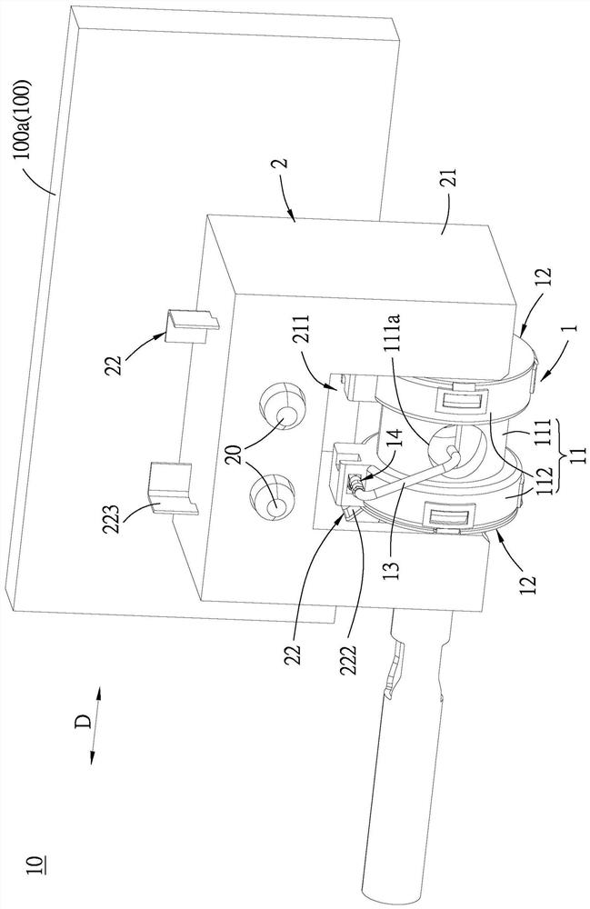
[0068] refer to Figure 1 to Figure 2 , an embodiment of the electrical connector assembly 10 of the present invention includes a first connector 1 and a second connector 2 .

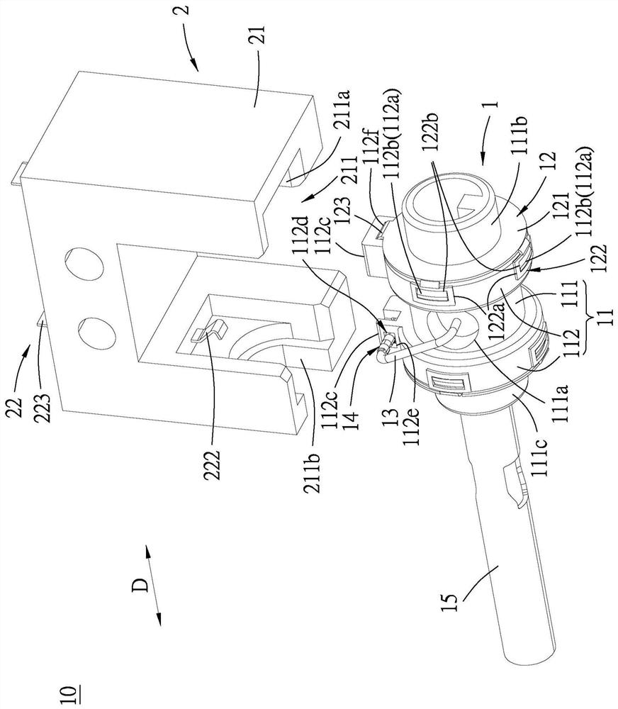
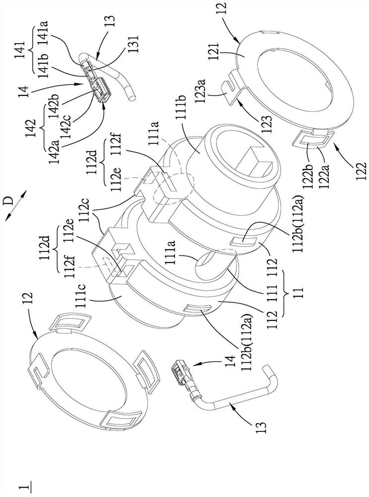
[0069] refer to Figure 2 to Figure 5 , the first connector 1 includes a rotating shaft 11 , two conductive rings 12 , two wires 13 , two connection terminals 14 , and an inner sleeve 15 . The rotating shaft 11 is, for example, made of insulating material such as plastic and includes a tube body 111 extending in an axial direction D, and an annular protrusion 112 formed on the outer peripheral surface of the tube body 111 . A plurality of conductive rings 12 are spaced apart from each other on the annular protrusion 112, and each conductive ring 12 has a contact ring surface 121 facing the axial direction D. In this embodiment, the annular protrusion The number of 112 is two, and two annular protrusions 112 are formed on the tube body 111 at intervals from each other, and two conductive rings 12 are r...


PUM


Abstract

The invention discloses an electric connector combination, which comprises a first connector and a second connector, wherein the first connector comprises a rotating shaft and a plurality of conductive rings, the rotating shaft comprises a pipe body extending in an axial direction and an annular convex part formed on the outer peripheral surface of the pipe body, the plurality of conductive ringsare arranged on the annular convex part at intervals, and each conductive ring is provided with a contact ring surface facing the axial direction; and the second connector comprises a plurality of conductive terminals respectively corresponding to the plurality of conductive rings, and each conductive terminal is provided with an elastic contact part which is in contact with the contact ring surface of the corresponding conductive ring in the axial direction. The conductive ring of the first connector and the conductive terminal of the second connector are in contact with each other in the axial direction, so that the situation of unstable contact during radial contact can be avoided.

Description

technical field [0001] The invention relates to an electrical connector combination, in particular to a rotary electrical connector combination. Background technique [0002] China Utility Model Patent Authorization Announcement No. CN206283084U discloses an electrical connector combination, which includes mutually butted terminals and a conductive ring. Two elastic contact parts that extend from the center line of rotation and are in sliding contact with the conductive ring. In such an electrical connector combination, the elastic contact portion is in contact with the conductive ring in the radial direction of the rotating shaft. The disadvantage of this radial contact method is that if the elastic contact portion of the terminal is not in contact with the maximum width portion of the conductive ring, it is easy to cause unstable contact, and if the rotation center of the shaft is shifted, it is easy to cause Bad contact problem. Contents of the invention [0003] The...

Claims


Application Information

Patent Timeline
Patent Type & Authority Applications(China)
IPC IPC(8): H01R39/64
CPCH01R39/64
Inventor 李新磊
Owner MOLEX INTERCONNECT SHANGHAI
Why Eureka
Try Eureka