Novel flange

A flange, a new type of technology, applied in the direction of flange connections, pipes/pipe joints/fittings, passing components, etc., can solve the problems of reducing engineering efficiency, slowing down construction progress, wasting manpower and material resources, etc., to improve engineering efficiency and speed up The effect of construction progress and installation is quick and convenient

Inactive Publication Date: 2020-10-30
韩国昊
View PDF5 Cites 4 Cited by
  • Summary
  • Abstract
  • Description
  • Claims
  • Application Information

AI Technical Summary

Problems solved by technology

Flange connection is an important connection method in pipeline construction. Flange connection is easy to use and can withstand high pressure. In industrial pipelines, flange connection is widely used. However, during the installation or disassembly of

Method used


Image

  • Novel flange
  • Novel flange
  • Novel flange

Examples


Embodiment Construction

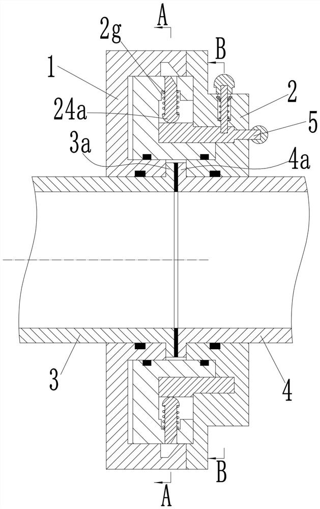
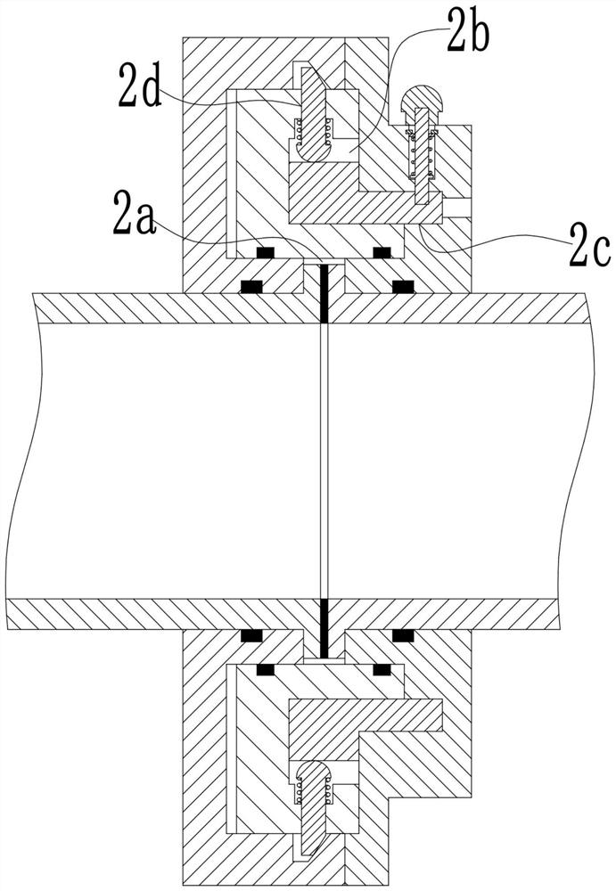
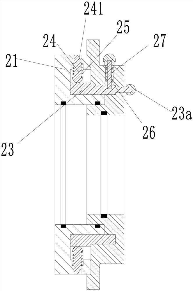
[0024] see Figure 1-10 As shown, a new type of flange is arranged between the left pipe 3 and the right pipe 4, including a left flange 1 and a right flange 2, the right end of the left flange 1 is provided with an annular slot 11, and the right The left end of the flange 2 is fixedly installed with an annular protrusion 21 for inserting into the annular slot 11, and the inner hole of the annular protrusion 21 forms a mounting groove 2a between the left flange 1 and the right flange 2, and the left The right end of pipeline 3 is radially provided with a left flange 3a extending into the installation groove 2a, and the left end of the right pipeline 4 is radially provided with a right flange 4a extending into the installation groove 2a; the annular slot 11 is provided with an annular locking groove 12 on the inner side wall; the right end surface of the annular protrusion 21 is provided with a first annular groove 2b, and the left end surface of the right flange 2 is provided ...


PUM


Abstract

The invention discloses a novel flange. The novel flange is arranged between a left pipeline and a right pipeline and comprises a left flange and a right flange, wherein an annular slot is formed in the right end of the left flange; an annular convex block is fixedly mounted at the left end of the right flange; a mounting groove is formed in an inner hole of the annular convex block; a left convexedge is arranged at the right end of the left pipeline; a right convex edge is arranged at the left end of the right pipeline; an annular locking groove is formed in the inner side wall of the annular slot; a first annular groove is formed in the right end surface of the annular convex block; a second annular groove is formed in the left end surface of the right flange; a plurality of radial holes are formed in the annular convex block; each radial hole is connected with a locking rod in a sliding manner; the inside of the first annular groove and the inside of the second annular groove are rotatably connected with a power ring; arc-shaped protrusions are arranged on the circumference side of the power ring; an arc-shaped groove is formed between two adjacent arc-shaped protrusions; an arc-shaped groove is formed in the right end surface of the right flange; and a handle is arranged at the right end of the power ring. The novel flange is simple in structure and is capable of achievingrapid connection.

Description

technical field [0001] The invention belongs to the technical field of pipeline connection devices, in particular to a novel flange. Background technique [0002] Flanges are also called flanges or flanges, parts that connect pipes to pipes. There are holes on the flange, and bolts can be worn. It usually refers to opening several holes for fixing on the periphery of a disc-like metal body for connecting other things. The existing flange connection is to fix two pipelines, pipe fittings or equipment respectively on a flange plate first, add flange pads between the two flange plates, and fasten them together with bolts to complete the connection. Flange connection is an important connection method in pipeline construction. Flange connection is easy to use and can withstand high pressure. In industrial pipelines, flange connection is widely used. However, during the installation or disassembly of ordinary flanges, bolts are required. It is time-consuming and labor-intensive ...

Claims


Application Information

Patent Timeline
IPC IPC(8): F16L23/04
CPCF16L23/04
Inventor 韩国昊李红生邵倩倩
Owner 韩国昊
Why Eureka
Try Eureka