Energy storage converter and system suitable for container energy storage

A technology for energy storage converters and containers, which is applied in the modification of power electronics, output power conversion devices, casings/cabinets/drawer parts, etc. Insufficient ventilation of energy storage converters, limited container space, etc.

Pending Publication Date: 2020-11-20
周锡卫
View PDF0 Cites 3 Cited by
  • Summary
  • Abstract
  • Description
  • Claims
  • Application Information

AI Technical Summary

Problems solved by technology

Since the temperature of the energy storage converter exceeds 60°C during operation, ventilation and cooling are required; for this, the existing technical design of the energy storage converter is based on the indoor installation and operation of the equipment room, with ample space, and the energy storage converter equipment is backed by the room On one side, there is enough space on the front and both sides of the equipment. In order to solve the problem of heat dissipation and ventilation during the operation of the energy storage converter, the scheduling design and structure of the front air at the lower end as the main, the side air at the lower end as the auxiliary, and the top air outlet are usually adopted. , this method has no problem in installation and use in equipment rooms with sufficient space, and can meet the requirements of ventilation and heat dissipation; however, when container energy storage systems are used in current and future large-scale battery energy storage system applications, due to the limited space of containers, energy storage cannot be guaranteed. There is enough ventilation space around the converter, resulting in insufficient ventilation of the energy storage converter, and the heat dissipation cannot meet the requirements, making the energy storage converter equipment unable to operate normally and posing safety hazards

Method used


Image

  • Energy storage converter and system suitable for container energy storage

Examples


Embodiment Construction

[0011] As an implementation example, an energy storage converter and system suitable for container energy storage will be described with reference to the accompanying drawings. However, the described embodiments are part of the embodiments of the present invention, not all of them. Based on the embodiments of the present invention, all other embodiments obtained by persons of ordinary skill in the art without making creative efforts belong to the protection scope of the present invention. The technology and solutions of the present invention are not limited to the content given in this embodiment example.

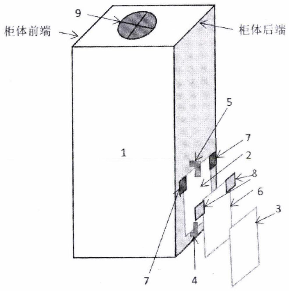
[0012] like figure 1 As shown, an energy storage converter and system suitable for container energy storage mainly includes: a converter cabinet (1), a vent on the rear side of the lower end of the converter cabinet (2), a converter cabinet The detachable cover plate at the lower end rear side (3), the detachable cover plate clamping position at the lower end rear side of ...


PUM


Abstract

The invention belongs to the technical field of battery energy storage system application, and particularly relates to an energy storage converter and system suitable for container energy storage. Inthe prior art, a container type energy storage system is usually adopted in large-scale storage battery energy storage system application, when an energy storage converter operates, the temperature often exceeds 60 DEG C and rises continuously, ventilation and cooling are required, but container space is limited, and enough ventilation space around the energy storage converter cannot be ensured, so that the problems that the energy storage converter is insufficient in ventilation and the heat dissipation cannot meet the requirements. A purpose of the invention is to solve the problems in the prior art. According to the invention, a ventilation opening is formed in the rear side of the lower end of an energy storage converter cabinet body, and is corresponding to the air inlet of a container, and the air inlet of the container is provided with a door capable of adjusting the air inflow, so that natural air outside the container can be fully utilized so as to meet heat dissipation of energy storage converter equipment, guarantee normal operation and save cooling power consumption inside the energy storage container.

Description

technical field [0001] The invention belongs to the technical field of application of battery energy storage systems, and in particular relates to an energy storage converter and system suitable for container energy storage. Background technique [0002] The application of large-scale energy storage is becoming more and more widespread, and the container energy storage system is convenient and fast to install on site, which is one of the main ways of battery energy storage application. Since the temperature of the energy storage converter exceeds 60°C during operation, ventilation and cooling are required; for this, the existing technical design of the energy storage converter is based on the indoor installation and operation of the equipment room, with ample space, and the energy storage converter equipment is backed by the room On one side, there is enough space on the front and both sides of the equipment. In order to solve the problem of heat dissipation and ventilation ...

Claims


Application Information

Patent Timeline
Patent Type & Authority Applications(China)
IPC IPC(8): H02M1/00H05K7/20H05K5/02
CPCH02M1/00H05K5/0213H05K7/20145H05K7/20172H05K7/20181H05K7/20909
Inventor 周锡卫
Owner 周锡卫
Why Eureka
Try Eureka