Low Profile Ultra Wideband Log Periodic Antenna Element

A logarithmic periodical antenna and ultra-wideband technology, applied in logarithmic periodical antennas, antennas, non-resonant long antennas, etc., can solve the problems of high frequency pattern cannot be improved, pattern and standing wave deterioration, narrow side coupling and other problems , to achieve the effect of small reflection loss, good applicability and high precision

Active Publication Date: 2022-05-17
10TH RES INST OF CETC
View PDF2 Cites 0 Cited by
  • Summary
  • Abstract
  • Description
  • Claims
  • Application Information

AI Technical Summary

Problems solved by technology

[0004] The purpose of the present invention is to solve the current traditional log-periodic antenna: (1) large size, (2) large narrow-side coupling, deterioration of pattern and standing wave (more obvious formation), (3) high-frequency pattern cannot be improved And other issues

Method used


Image

  • Low Profile Ultra Wideband Log Periodic Antenna Element
  • Low Profile Ultra Wideband Log Periodic Antenna Element
  • Low Profile Ultra Wideband Log Periodic Antenna Element

Examples


Embodiment Construction

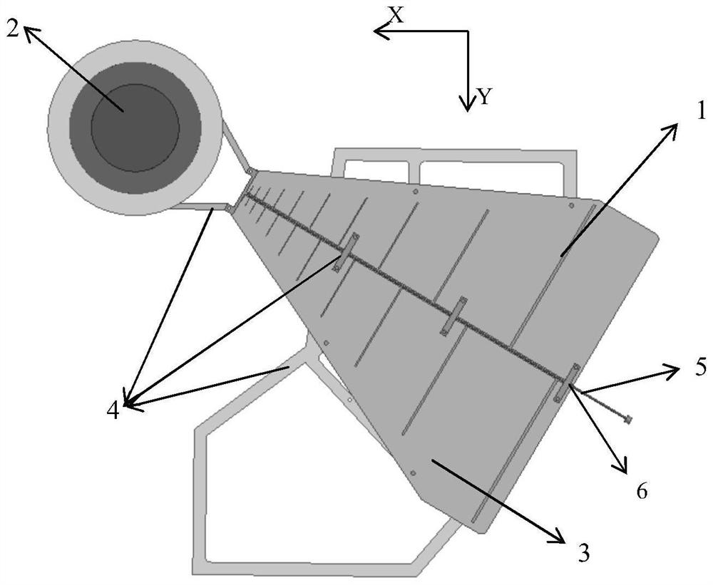
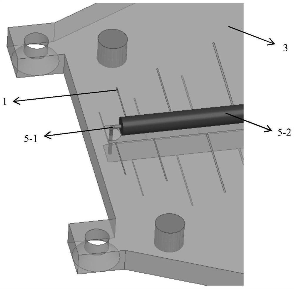
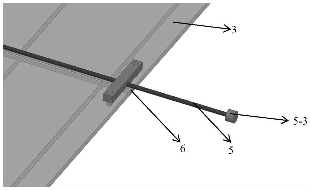
[0021] refer to Figure 1 ~ Figure 4. In the preferred embodiment described below, a low-profile ultra-wideband log-periodic antenna unit based on a graded-index lens includes: N parallel arrangements connected to a pair of two-wire transmission lines, that is, a collection line, and the feed source is connected to the shortest At one end of the vibrator, two adjacent vibrators are cross-fed and printed on a plane dipole (1) on a dielectric substrate (3), and a radio frequency coaxial cable (5) is supported on the center line of the dielectric substrate (3). The matching branches of the dipole arm of the ultra-broadband printed logarithmic periodic planar dipole (1) are alternately printed on both sides of the axisymmetric center line of the collection line, and the outer conductor (5-2) of the radio frequency coaxial cable (5) passes through the medium The chip resistor (6) arranged at the end of the longest vibrator at the end of the wide-side assembly line of the substrate...


PUM


Abstract

The invention discloses a low-profile ultra-wideband logarithmic periodic antenna unit, which aims to provide a logarithmic periodic antenna unit with narrower high-frequency pattern beams and higher gain. The present invention is realized through the following technical scheme: the pair of long dipole arm matching branches of the ultra-broadband printed logarithmic periodic planar dipole are respectively printed alternately on both sides of the axisymmetric central line of the collection line, and the radio frequency coaxial cable is suspended in the air through the outer conductor Supported on the center line of the dielectric substrate, the outer conductor realizes impedance matching through the chip resistor arranged at the longest vibrator end of the broadside collection line terminal of the dielectric substrate, and the gradient index lens fixed on the narrow side plane dipole loads the pair The standing wave characteristics of several-period antennas focus on the high-frequency beams to realize the elevation plane beams that only converge on the high-frequency beams; after feeding, the electromagnetic energy is transmitted along the collection line, and the vibrators in the excitation area are excited in turn, and the transmission line propagates The guided wave is transformed into an unbounded medium and propagates in the horizontal direction diagram as 360° uniform radiation.

Description

technical field [0001] The invention relates to a low-profile ultra-wideband logarithmic periodic antenna unit LPDA (Log-Periodicdipoleantenna) based on a graded-refractive-index lens, which is suitable for application in the fields of navigation, detection, and ultra-wideband (UWB) communication. Background technique [0002] The logarithmic periodic antenna LPDA is an antenna designed based on the principle of scaling. All the dimensions of the vibrator and the distance between the vibrator have a certain proportional relationship. Its characteristic is that it changes periodically with the logarithm of the frequency. It is a non-frequency variable antenna. The so-called non-frequency variable means that the electrical characteristics of the antenna such as impedance, pattern, gain, and standing wave ratio change periodically with the logarithm of the frequency, and remain basically unchanged in a wide frequency band. . With the development of modern communication technol...

Claims


Application Information

Patent Timeline
Patent Type & Authority Patents(China)
IPC IPC(8): H01Q1/36H01Q1/38H01Q1/50H01Q11/10H01Q15/02
CPCH01Q11/10H01Q1/38H01Q1/50H01Q15/02H01Q1/36Y02D30/70
Inventor 陈晨黄明乔文昇孙超朱军
Owner 10TH RES INST OF CETC
Why Eureka
Try Eureka