Clutch control mechanism and vehicle

A technology of clutch control and release bearing, applied in the direction of clutch, electric clutch, mechanical drive clutch, etc., can solve the problems of skew of lever actuator, uneven force on clutch and release bearing, etc., to avoid skew, act quickly, and satisfy Fast separation effect

Active Publication Date: 2022-04-15
BYD CO LTD
View PDF6 Cites 0 Cited by
  • Summary
  • Abstract
  • Description
  • Claims
  • Application Information

AI Technical Summary

Problems solved by technology

[0005] The technical problem to be solved by the present invention is: in view of the existing clutch control device, the lever actuator may be skewed during the process of being pushed, so that the force on each point at the level where the clutch contacts the release bearing is not uniform, and provides A clutch control mechanism and vehicle

Method used


Image

  • Clutch control mechanism and vehicle
  • Clutch control mechanism and vehicle
  • Clutch control mechanism and vehicle

Examples


no. 1 example

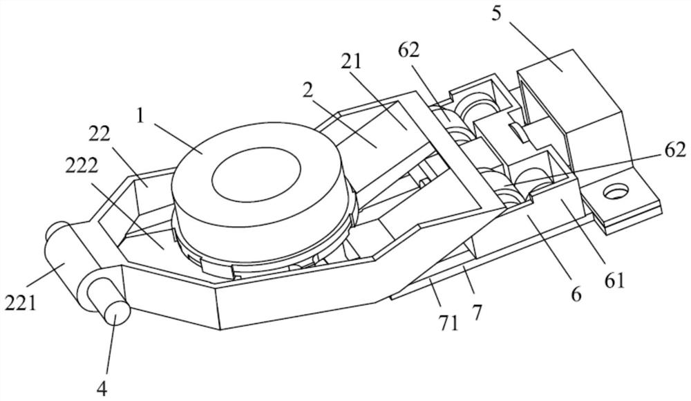
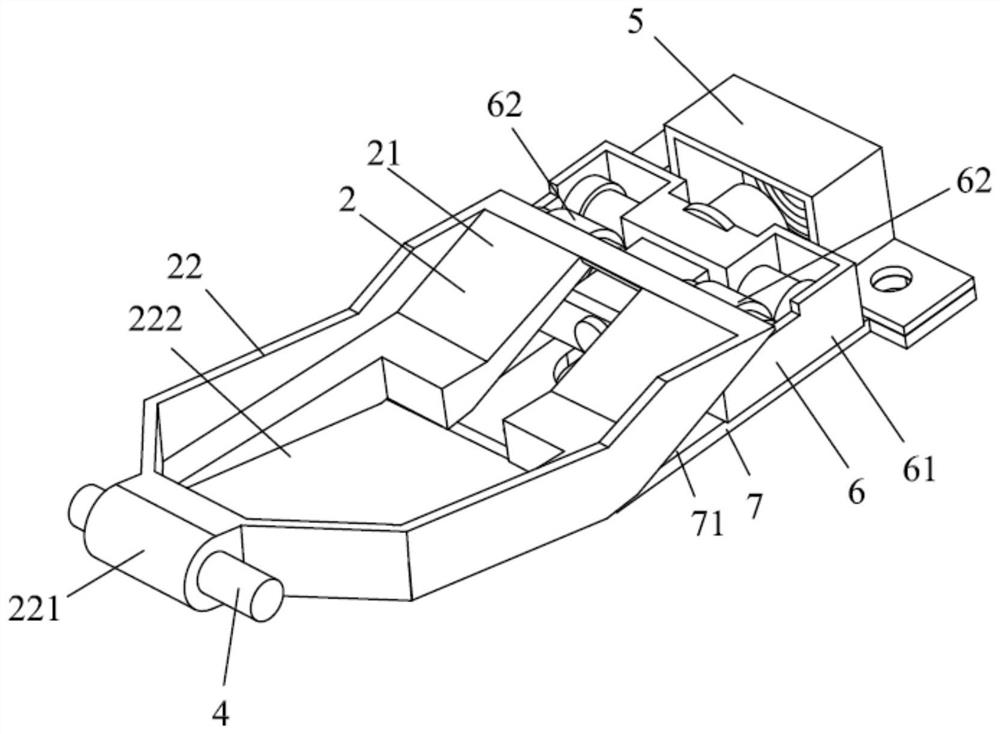
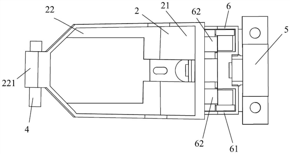
[0052] Such as Figure 1 to Figure 9 As shown, the first embodiment of the present invention provides a clutch control mechanism, including a release bearing 1, an actuator frame 2 and a driving device. The actuator frame 2 includes a rolling plate 21 and a support frame 22 for placing and supporting the release bearing 1, the first end of the support frame 22 is connected to the rolling plate 21 (fixedly connected or integrally formed), The second end of the support frame 22 is rotatably connected to the transmission case through the support pin shaft 4 . The driving device applies a driving force to the actuator frame to make the actuator frame 2 swing around the axis of the support pin shaft 4, thereby pushing the release bearing 1 to move toward or away from the clutch, so as to control the clutch joining or disengaging.

[0053] In the first embodiment, the rolling plate end of the actuator frame 2 is a rolling plate 21 .

[0054] In some alternative solutions, the rol...

no. 2 example

[0088] Figure 10 The clutch control mechanism provided for the second embodiment of the present invention is different from the first embodiment in that the second end of the raceway extends below the bottom surface of the support frame 22, and the rolling member 62 is in the position When the first end of the raceway is in contact with the highest point of the bottom surface of the rolling plate 21, the rolling member 62 is in contact with the bottom surface of the support frame 22 when it is in the second end of the raceway. The bottom surface of the support frame 22 and the bottom surface of the rolling plate 21 transition through an arc. When the rolling element 62 moves to the inflection point, the speed of the rolling element 62 remains stable, the motor is controllable (providing appropriate driving force), and the clutch is kept engaged.

[0089] The arc surface protrudes toward the biasing direction of the rolling element 62 . The angle between the bottom surface o...

no. 3 example

[0095] Figure 11 to Figure 15 Shown is the clutch control mechanism provided by the third embodiment of the present invention, which differs from the first embodiment in that:

[0096] (1) The support element is an arc-shaped bump 30, which is integrally formed on the top surface of the support frame 22, and the side surfaces other than the top surface of the arc-shaped bump 30 are limited. position hole 301, the claw portion 91 of the release bearing bottom plate 9 is provided with a mounting hole 92, and the clutch control mechanism also includes a snap spring 40 clamped between the release bearing bottom plate 9 and the release bearing 1, the clip The locking feet of the spring 40 are inserted into the installation hole 92 and the limiting hole 301 to limit the displacement of the release bearing bottom plate 9 and the release bearing 1 outside the axial direction. That is, the release bearing base plate 9 and the release bearing 1 cannot rotate around the guide shaft 8 ....


PUM


Abstract

The invention belongs to the technical field of clutch operating mechanisms, and in particular relates to a clutch control mechanism and a vehicle. The clutch control mechanism includes: a release bearing; On the transmission case; the driving device, which makes the actuator frame swing around the axis of the support pin shaft by applying a driving force to the actuator frame; the support element, the separation bearing bottom plate and the guide shaft, the support element is fixed or integrally formed on the support frame, the release bearing bottom plate is fixedly connected to one end of the release bearing and hinged to the support frame, the radially outer side of the release bearing bottom plate is provided with claws, and the support element The top surface contacts the claw supporting the release bearing base plate. In the clutch control mechanism of the present invention, the release bearing is always kept horizontal during the process of being pushed, and the force is evenly applied to all points on the level where the clutch is in contact with the release bearing.

Description

technical field [0001] The invention belongs to the technical field of clutch operating mechanisms, and in particular relates to a clutch control mechanism and a vehicle. Background technique [0002] An existing operating device for a friction disc clutch comprises: a lever actuator; an operating device for turning the lever actuator around a turning axis so that force is applied by means of the lever actuator to the friction disc clutch; and, a reset means for applying a reset torque to the lever actuator about the rollover axis. Furthermore, a damping device is provided for applying a predetermined damping torque to the lever actuator about the pivot axis. The actuating device has a roller which is arranged between the lever actuator and an abutment element and which can be moved along the lever actuator in order to vary the distance between the abutment element and the lever actuator. [0003] With this type of clutch actuating device, by actuating the actuator, the ro...

Claims


Application Information

Patent Timeline
Patent Type & Authority Patents(China)
IPC IPC(8): F16D28/00F16D23/14
CPCF16D28/00F16D23/14
Inventor 廉玉波凌和平翟震熊雨超王文静
Owner BYD CO LTD
Why Eureka
Try Eureka