Steel bar mesh clamping device and steel bar mesh cage forming equipment

A steel mesh and clamping device technology, which is applied to ceramic molding machines and manufacturing tools, can solve the problems of inconvenient operation and low production efficiency of steel mesh cages

Active Publication Date: 2021-06-25
GUANGDONG BOZHILIN ROBOT CO LTD
View PDF6 Cites 3 Cited by
  • Summary
  • Abstract
  • Description
  • Claims
  • Application Information

AI Technical Summary

Problems solved by technology

[0004] The purpose of this application is to provide a steel mesh clamping device and steel mesh cage forming equipment to solve the problems of inconvenient operation and low production efficiency of the steel mesh cage network in the prior art

Method used


Image

  • Steel bar mesh clamping device and steel bar mesh cage forming equipment
  • Steel bar mesh clamping device and steel bar mesh cage forming equipment
  • Steel bar mesh clamping device and steel bar mesh cage forming equipment

Examples


Embodiment

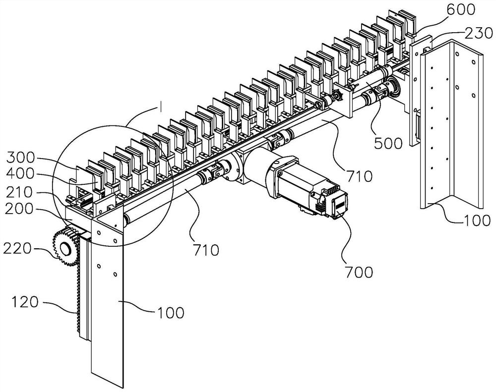
[0047] The steel mesh cage in the autoclaved aerated concrete slab is generally formed by connecting pairs of steel mesh sheets 800 through a plurality of buckles, and each buckle is respectively snapped to the edge longitudinal bars of two steel mesh sheets 800, so that the two The steel mesh sheets 800 are kept at a certain distance and fixedly connected as a whole, thereby forming a steel mesh cage.

[0048] In the prior art, generally by manual operation, the distance between two opposite steel mesh sheets 800 is first adjusted according to the size of the mesh cage, and then the buckles are respectively snapped into the longitudinal reinforcement bars 810 of the two steel mesh sheets 800 by using a steel bar networking device. . When the buckle is installed, the longitudinal steel bar 810 is easily bent and deformed under the force, which makes it difficult to be buckled into the buckle, resulting in low production efficiency and low yield.

[0049] It should be noted th...


PUM


Abstract

The invention relates to the technical field of steel bar networking, in particular to a steel bar mesh clamping device and steel bar mesh cage forming equipment. The steel bar mesh cage forming equipment comprises a steel bar networking device and a steel bar mesh clamping device, wherein the steel bar mesh clamping device is used for clamping at least two steel bar meshes, and the steel bar networking device is used for clamping buckles into longitudinal steel bars at the lowermost ends of the steel bar meshes. The steel bar mesh clamping device comprises a base, at least two fixing plates, at least two push plates and a clamping driving mechanism; the at least two fixing plates are arranged in parallel and are fixed to the base at intervals; the at least two push plates and the at least two fixing plates are arranged in a staggered manner; and the clamping driving mechanism is installed on the base, the output end of the clamping driving mechanism is connected with the at least two push plates, and the clamping driving mechanism is used for driving the at least two push plates to move, so that each push plate is matched with the adjacent fixing plate to clamp the longitudinal steel bar at the lowest end of one steel bar mesh, the longitudinal steel bar at the lowest end is not prone to bending deformation or displacement when stressed, the clamping success rate of the buckles is high, and the yield and the production efficiency can be improved.

Description

technical field [0001] The present application relates to the technical field of reinforcement netting, in particular, to a reinforcement mesh clamping device and reinforcement cage forming equipment. Background technique [0002] In the production process of autoclaved aerated concrete slabs, it is necessary to add steel mesh cages to the slabs to enhance its structural stability. During manufacture, single pieces of steel mesh sheets are combined into steel mesh cages, and then the steel mesh cages are hung on steel The brazing is inserted into the pouring formwork. [0003] When the steel mesh cage is networked, the positions of the paired steel mesh pieces are manually adjusted according to the size of the steel mesh cage, and then the buckles are snapped into the longitudinal bars of the steel mesh pieces. When snapping buckles into the longitudinal bars of the steel mesh sheet, due to the large force, the longitudinal bars are easily bent and deformed and difficult to...

Claims


Application Information

Patent Timeline
Patent Type & Authority Applications(China)
IPC IPC(8): B28B23/04B28B23/22B28B23/00
CPCB28B23/04B28B23/22B28B23/00
Inventor 邬全兵张琼李宁
Owner GUANGDONG BOZHILIN ROBOT CO LTD
Why Eureka
Try Eureka