Amblyopia and myopia comprehensive treatment instrument

A technology for comprehensive treatment and myopia, applied in the field of medical devices, can solve the problem that a single light source system cannot switch between different treatment modes, and achieve the effects of cost saving, soft material, and simple design structure

Active Publication Date: 2022-03-18
JIANGXI ZHONGLAN ELECTRONICS MFG CO LTD
View PDF0 Cites 0 Cited by
  • Summary
  • Abstract
  • Description
  • Claims
  • Application Information

AI Technical Summary

Problems solved by technology

[0004] In view of the above-mentioned shortcomings of the prior art, the purpose of the present invention is to provide a comprehensive treatment instrument for amblyopia and myopia, which is used to solve the problem that the single light source system of the treatment instrument in the prior art cannot switch between different treatment modes

Method used


Image

  • Amblyopia and myopia comprehensive treatment instrument
  • Amblyopia and myopia comprehensive treatment instrument
  • Amblyopia and myopia comprehensive treatment instrument

Examples


Embodiment 1

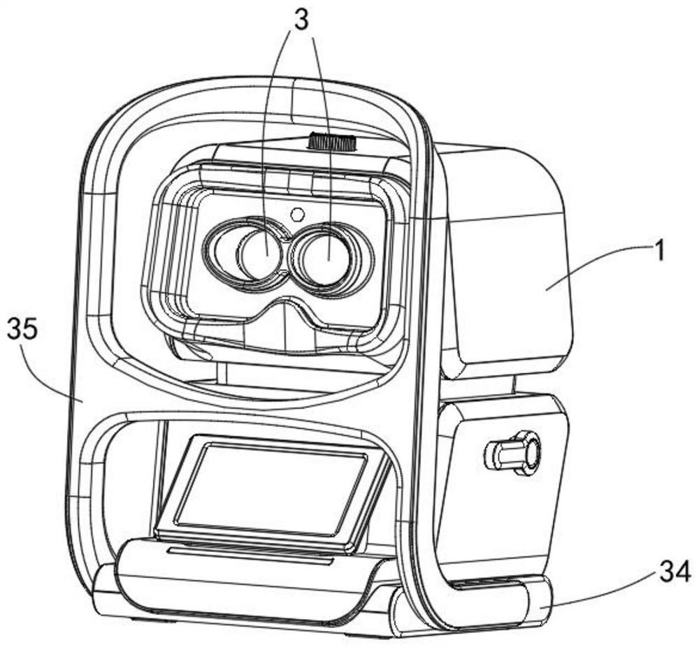
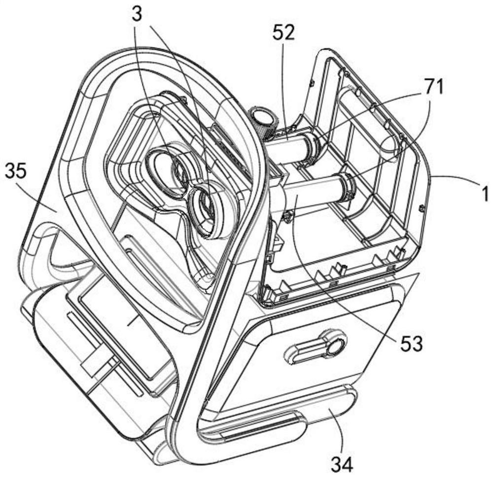
[0050] Example 1, please refer to figure 1 and figure 2 , the present invention provides an embodiment of a comprehensive therapeutic apparatus for amblyopia and myopia. The function of support and protection, the outer casing 1 is provided with a viewing window 3, the viewing window 3 allows the user to look into the interior of the outer casing 1 from the outside of the outer casing 1, and the optical path tube includes The first optical path barrel 52 and the second optical path barrel 53, the first optical path barrel 52 and the second optical path barrel 53 are arranged in parallel inside the outer shell 1, the first optical path barrel 52 and the second optical path barrel 53 The optical path cylinder 53 can adjust the relative distance by controlling, thereby realizing the adjustment of the interpupillary distance, the position of the output end of the first optical path cylinder 52 and the second optical path cylinder 53 corresponds to the position of the viewing win...

Embodiment 2

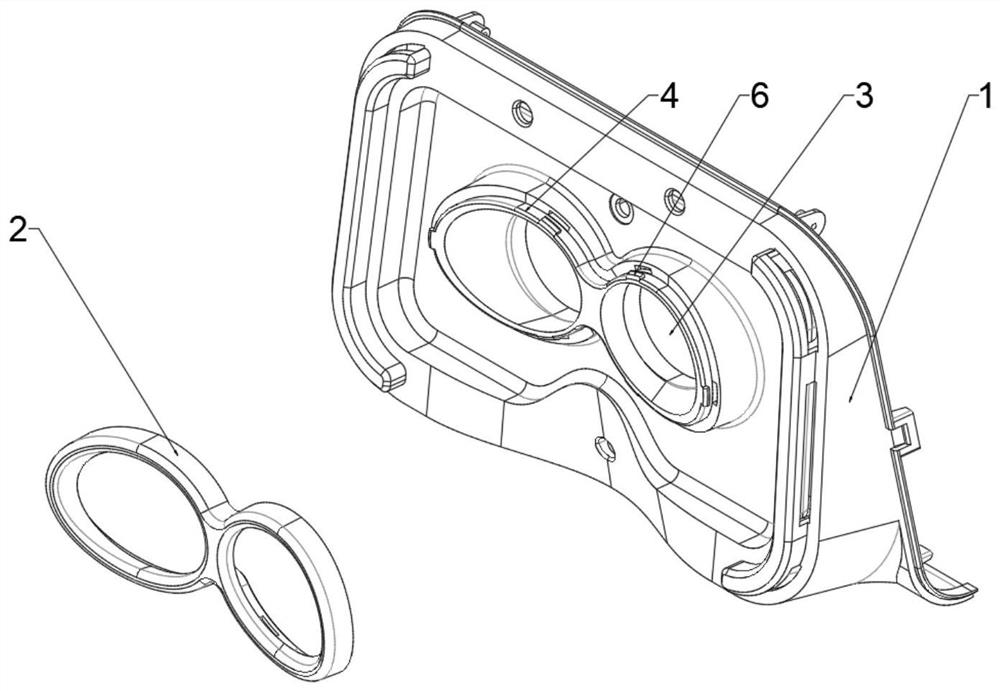
[0051] Example 2, please refer to image 3 and Figure 4 , the orbital pad 2 is detachably installed on the edge of the viewing window 3, the orbital pad 2 is made of soft material, the material of the orbital pad 2 can be selected from materials such as silica gel or rubber, and the material is soft and It is more friendly to the user's skin; the edge of the viewing window 3 can be provided with a rib structure 4, one side of the orbital pad 2 can be provided with a groove 5, and the other side of the orbital pad 2 is used for contact with the user. Contact, the rib structure 4 can be embedded in the groove 5; the side of the rib structure 4 can be provided with a clip 6, the outer side of the clip 6 is a guide side, and the guide side The surface of the surface can be an arc or an inclined surface. One side of the inner side of the clamp 6 is a locking side, the guiding side is a small end, the locking side is a large end, and the inner side wall of the groove 5 A card slo...

Embodiment 3

[0052] Embodiment 3, the orbital pad 2 is non-detachable and installed on the edge of the viewing window 3. The specific non-detachable method can be molded integrally, or by riveting, or by gluing and other forms to complete the installation. This non-detachable The design of the dismounting installation method is conducive to the stability of the instrument structure and reduces the difficulty of equipment processing. The orbital pad 2 is made of soft materials, and the material of the orbital pad 2 can be selected from materials such as silica gel or rubber. Softer and more friendly to the user's skin.


PUM


Abstract

The invention provides a comprehensive treatment instrument for amblyopia and myopia, which relates to the technical field of medical devices, and is used to solve the problem in the prior art that the treatment instrument adjusts the incident light through a single light source to achieve treatment, and the types of output treatment light are limited, and different treatment modes cannot be switched. The problem includes: an outer casing, an optical path barrel and a multi-light source emitting device, the outer casing is provided with a viewing window; the optical path barrel includes a first optical path barrel and a second optical path barrel, and the first optical path barrel and the second optical path barrel The positions of the output ends of the two optical path tubes correspond to the positions of the viewing windows; the multi-light source emitting device can emit light of different types or different combinations into the interior of the optical path tubes. Compared with the traditional single light source output type therapeutic apparatus, the present invention can output various types or different combinations of light for different types of amblyopia and myopia of each patient, so as to achieve corresponding accurate treatment for different types of eye problems effect, wider applicability.

Description

technical field [0001] The invention relates to the technical field of medical devices, in particular to a comprehensive treatment instrument for amblyopia and myopia. Background technique [0002] In the past ten years, a large number of studies on student myopia and animal models of myopia at home and abroad suggest that the occurrence and development of students' acquired myopia are mainly related to one main cause: seeing near, and two key links: defocusing after seeing near and after focusing (that is, adjustment). hysteresis) related. Professor Xu Guangji, the leader of the myopia prevention and control expert group for former Chinese students, also pointed out that "seeing near", such as reading, writing, watching TV and computer, is the main reason for the occurrence and development of myopia. When the human eye looks close, the central area is clear, but the peripheral vision is not clear. After being in the defocused state of the peripheral vision, it can lead to ...

Claims


Application Information

Patent Timeline
Patent Type & Authority Patents(China)
IPC IPC(8): A61F9/00A61N5/06A61N5/067F16H19/04
CPCA61F9/00A61N5/0613F16H19/043A61F2009/0035A61N2005/0651A61N2005/0663
Inventor 李平
Owner JIANGXI ZHONGLAN ELECTRONICS MFG CO LTD
Why Eureka
Try Eureka