Auxiliary supporting protection device for computer

A technology of auxiliary support and protection device, which is applied to the frame of the engine, supporting machines, mechanical equipment, etc., can solve the problems of inconvenient adjustment, fixed structure, and inflexibility, and achieve the effect of convenient protection, convenient adjustment, and improved use flexibility.

Pending Publication Date: 2021-10-22
汪衍燕
View PDF0 Cites 0 Cited by
  • Summary
  • Abstract
  • Description
  • Claims
  • Application Information

AI Technical Summary

Problems solved by technology

[0005] The purpose of the present invention is to solve the disadvantages of the existing computer protection and support devices in the prior art, most of which are fixed in structure, inconvenient to adjust, single in use mode, and not flexible enough, and propose an auxiliary support and protection device for computers

Method used


Image

  • Auxiliary supporting protection device for computer
  • Auxiliary supporting protection device for computer
  • Auxiliary supporting protection device for computer

Examples


Embodiment 1

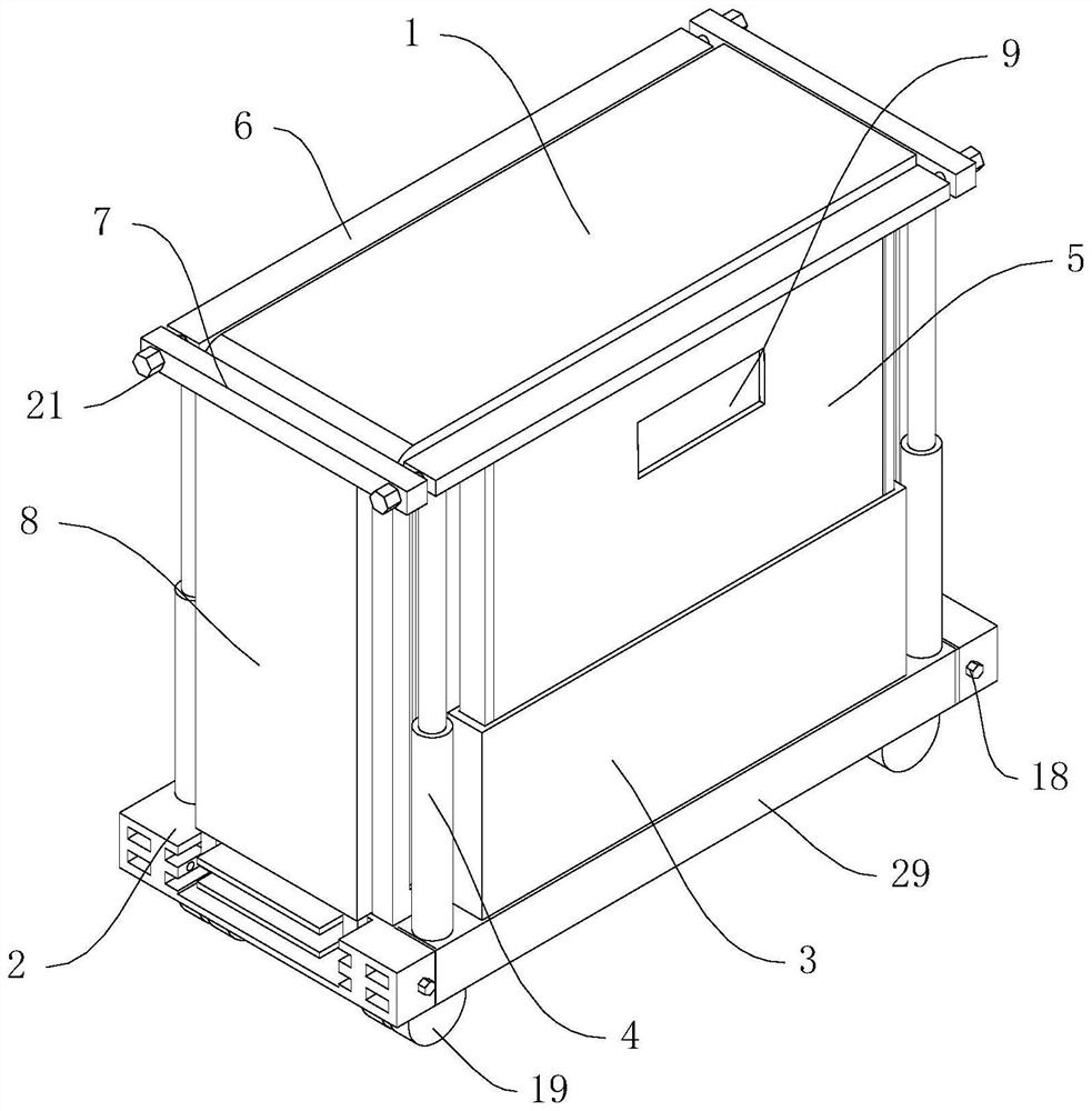
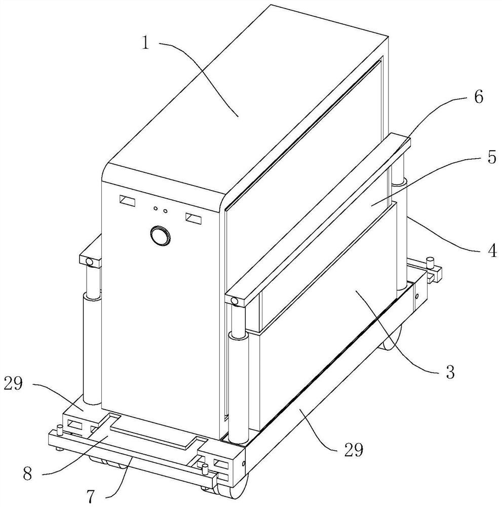
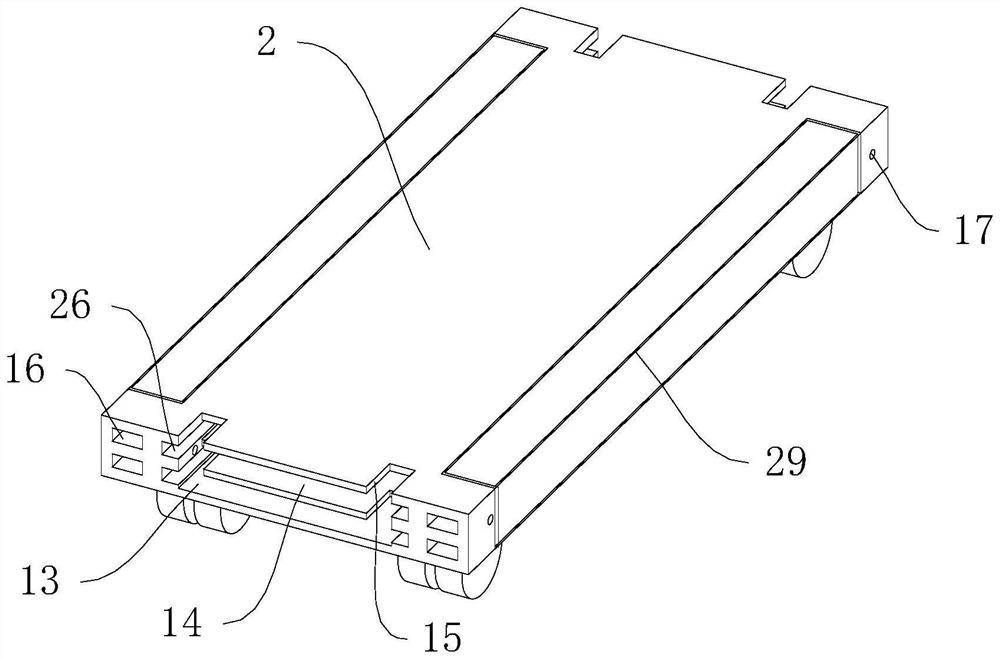
[0030] refer to Figure 1-10 , an auxiliary support protection device for computers, including a chassis 1, a base 2 is installed at the bottom of the chassis 1, a moving wheel 19 is installed at the bottom of the base 2, an installation groove 13 is opened through the bottom of the base 2, and a partition is installed inside the installation groove 13. Plate 14, the partition is located in the middle of the installation groove 13, and both sides of the installation groove 13 are inserted with protective plates 8 to facilitate the protection of the chassis 1. The protective plates 8 are arranged symmetrically along the two sides of the partition 14, and one end of the protective plate 8 Both stretch out the outside of the base 2, and the end of the protective plate 8 located at the outside of the base 2 is equipped with a clamping plate 7, and both sides of the opposite end of the protective plate 8 and the clamping plate 7 are equipped with a limit block 23, and the limit bloc...

Embodiment 2

[0033] refer to Figure 1-5 , as another preferred embodiment of the present invention, the difference from Embodiment 1 is that the sliding adjustment mechanism includes a sliding column 24, a third limiting hole 25, a slide groove 26, a second limiting hole 17 and a second limiting bolt 18. The chute 26 is opened on both sides of the installation groove 13, and the chute 26 is arranged symmetrically along the two sides of the partition 14, and the slid column 24 is fixed at both ends of the side of the limit block 23 opposite to the chute 26, and the third limit The hole 25 is provided on the opposite side of the stop block 23 and the chute 26, and the third stop hole 25 is located between the sliding posts 24, the second stop hole 17 is opened on both sides of the base 2, and the second stop bolt 18 is plugged into the second limiting hole 17, slidingly connected between the sliding column 24 and the sliding groove 26, and the spacing between adjacent sliding columns 24 mat...

Embodiment 3

[0035] When the single integral adjustment plate 5 extends out of the base plate 3, it does not come into contact with the chassis 1, and its protective effect is relatively poor. Refer to Figure 6-8 , as another preferred embodiment of the present invention, the difference from Embodiment 1 is that the adjusting plate 5 includes a fixed plate 501, a moving plate 502 and a mounting frame 503, the mounting frame 503 is a rectangular structure, and the mounting frame 503 is slidably installed on the base plate 3 Inside, the fixed plate 501 is installed on the side of the installation frame 503 opposite to the chassis 1, and the movable plate 502 is slidably installed on the side opposite to the fixed plate 501 inside the installation frame 503. The fixed plate 501 is evenly opened along the length direction. a plurality of through-hole slots 11, the moving plate 502 is evenly equipped with a plurality of elastic posts 12 along the length direction, the positions of the elastic p...


PUM


Abstract

The invention relates to the technical field of protection devices, in particular to an auxiliary supporting protection device for a computer. The auxiliary supporting protection device comprises a case, a base is mounted at the bottom of the case, a mounting groove is formed in the bottom of the base in a penetrating manner, a partition plate is mounted in the mounting groove, and protection plates are inserted into two sides in the mounting groove and are symmetrically arranged along two sides of the partition plate; one ends of the protection plates extend outside of the base, clamping plates are mounted at the ends, located outside the base, of the protection plates, limiting blocks are mounted on the two sides of the ends, opposite to the clamping plates, of the protection plates, sliding adjusting mechanisms are mounted between the limiting blocks and the mounting grooves and between the limiting blocks and the base, base plates are mounted on the two sides of the top of the base, and the base plates are located on the two sides of the case; and adjusting columns are installed on the outer sides of the two ends of the base plates, the tops of the base plates are sleeved with adjusting plates, connecting rods are installed on the tops of the adjusting plates, the two ends of the connecting rod are connected with the tops of the adjusting columns, and limiting mechanisms are installed between the connecting rods and the clamping plates. Adjustment is convenient, and the protection effect is good.

Description

[0001] This application is a divisional application, the original patent number is: 202010780812.8, the application date is August 6, 2020, and the title of the invention is: an auxiliary support and protection device for a computer case. technical field [0002] The invention relates to the technical field of protection devices, in particular to an auxiliary support protection device for computers. Background technique [0003] Computer, commonly known as computer, is a modern electronic computing machine used for high-speed computing. It can perform numerical calculations, logic calculations, and storage and memory functions. It is a modern intelligent electronic device that can run according to programs and process massive amounts of data automatically and at high speed. Equipment is composed of hardware system and software system, and computer case is one of the important devices composed of computer. [0004] Most of the existing computer cases are directly placed on th...

Claims


Application Information

Patent Timeline
Patent Type & Authority Applications(China)
IPC IPC(8): F16M3/00F16F15/04
CPCF16M3/00F16F15/04
Inventor 不公告发明人
Owner 汪衍燕
Why Eureka
Try Eureka