A safe hot and cold water faucet

A technology of hot and cold water and faucets, which is applied in the field of faucets, can solve the problems of hot and cold water faucets being scalded, low control precision, and the inability to clean faucets and faucets, etc., to achieve the effects of preventing scalding accidents, accurate output ratio, and safe use

Active Publication Date: 2021-12-17
徐州普拓机械科技有限公司
View PDF6 Cites 0 Cited by
  • Summary
  • Abstract
  • Description
  • Claims
  • Application Information

AI Technical Summary

Problems solved by technology

[0005] In order to solve the above technical problems, the present invention provides a safe cold and hot water faucet to solve the problem that existing hot and cold water faucets are prone to scald accidents, have low control precision, cannot clean impurities in the faucet and keep the inside of the faucet clean, and cannot pass through the bubbles. Ways to Conserve Water Problems

Method used


Image

  • A safe hot and cold water faucet
  • A safe hot and cold water faucet
  • A safe hot and cold water faucet

Examples


Embodiment 1

[0077] as attached figure 1 to attach Figure 12 Shown:

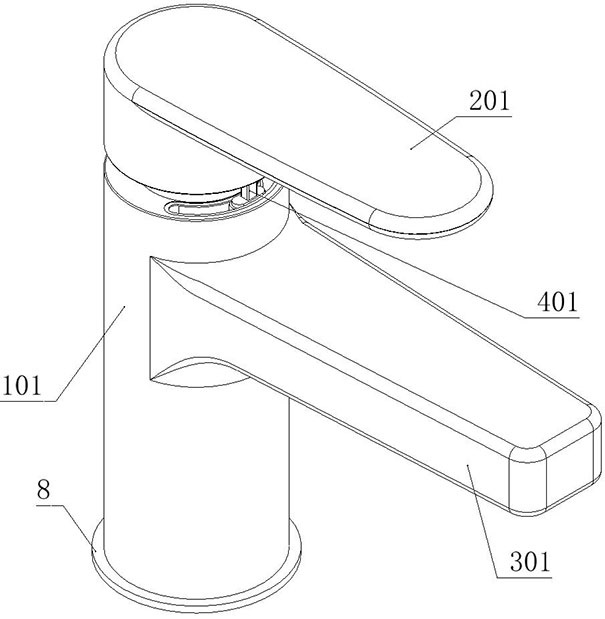
[0078] The present invention provides a safe hot and cold water faucet, which includes a main body device 1;

[0079] A sealing ring 8 is installed on the bottom of the main device 1; a control device 2 is installed on the main device 1; a water passage device 3 is fixedly connected to the main device 1, and a support device 5 is fixedly connected inside the water passage device 3; There is a driving part 6; an adjustment control part 4 is installed on the main device 1; the control device 2 includes: a control handle 201, which is provided with a valve body installation hole 205; a centering chute 202, which is set on On the rear side of the control handle 201, the centering chute 202 is a concave arc-shaped structure; the positioning hole 203 is set in the middle of the centering chute 202; the homing device 7 is fixedly connected to the main device 1 superior.

[0080] as attached Figure 4 , attached Figure 5...

Embodiment 2

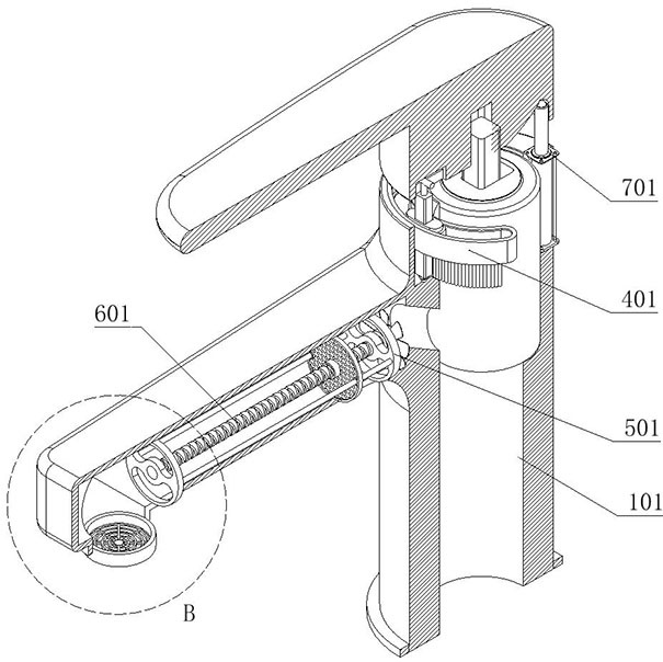
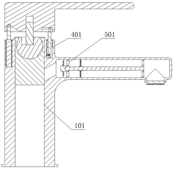
[0083] as attached Figure 8 , attached Figure 9 As shown, the adjustment control part 4 includes: an arc track 401, which is fixedly connected to the top of the control installation groove 103; There is a rectangular through hole on the top; the adjustment control part 4 also includes: a lifting trigger rod 403, which is slidably set in the rectangular through hole of the moving slider 402; a linkage rod 404, which is a "T" shaped structure, And the linkage rod 404 is fixedly connected to the lifting trigger rod 403; the top of the linkage rod 404 is slidably connected to the adjustment chute 204; the wave plate 405, the wave plate 405 is fixedly connected to the bottom of the arc track 401; the controller 406, the controller 406 is fixed Connected to the lower part of the lifting trigger lever 403; trigger switch 407, the trigger switch 407 is fixedly connected to the bottom of the lifting trigger lever 403; the adjustment control part 4 also includes: an adjustment spring...

Embodiment 3

[0085] On the basis of Embodiment 1, this embodiment provides another structural form of positioning ball 702 to solve the problem of serious wear and tear of positioning ball 702 after long-term use. The homing device 7 includes: electric telescopic rod 701, which is fixed Connected to the main pipe 101; the positioning ball 702, the positioning ball 702 is set on the shaft end of the electric telescopic rod 701; by installing a rubber pad on the surface of the positioning ball 702 or directly replacing the positioning ball 702 with a high-hardness rubber ball, the positioning is reduced. The wear of the ball 702 improves the service life of the positioning ball 702 .


PUM


Abstract

The invention provides a safe hot and cold water faucet, which relates to the technical field of faucets; it solves the problem that the existing hot and cold water faucets are prone to scalding accidents, have low control precision, cannot clean impurities in the faucet, and cannot save water by foaming The problem includes the main device; a sealing ring is installed at the bottom of the main device; a control device is installed on the main device; a water passage device is fixedly connected to the main device, and a support device is fixedly connected inside the water passage device; The driving part; the main device is equipped with an adjustment control part; a control device is provided, wherein the control device adopts a control handle with a centering chute and a reset device that can quickly realize the downward extrusion of the control handle And homing, avoiding the problem that the current hot water pipe outlet water is very timely but very easy to scald different users.

Description

technical field [0001] The invention belongs to the technical field of faucets, and belongs to IPC classification F16K, and more specifically relates to a safe cold and hot water faucet. Background technique [0002] Water tap is the popular title of water valve, which is used to control the size switch of water flow and has the effect of saving water. As we all know, our life is inseparable from water, which means that people need to be in contact with various faucets and valves. The replacement speed of faucets is very fast, from old-fashioned cast iron technology to electroplating knob type, and to stainless steel single temperature Single control faucet, stainless steel dual temperature dual control faucet, kitchen semi-automatic faucet. Now, more and more consumers choose faucets, they will comprehensively consider the material, function, shape and other aspects. The bottom of the lower ceramic spool is composed of three holes, two of which are used for cold water in ...

Claims


Application Information

Patent Timeline
Patent Type & Authority Patents(China)
IPC IPC(8): F16K1/36F16K1/32F16K27/02F16K31/60F16K31/02E03C1/084
CPCF16K1/36F16K1/32F16K27/02F16K31/60F16K31/02E03C1/084Y02A20/411
Inventor 邵帅
Owner 徐州普拓机械科技有限公司
Why Eureka
Try Eureka