

New-core heat exchanger and its making process
A technology of heat exchangers and heat exchange tubes, applied in indirect heat exchangers, heat exchanger types, lighting and heating equipment, etc., can solve the problems of large heat exchangers, large temperature differences between inner and outer walls, and large demand for heat sources, etc. Problems, to achieve the effect of advanced processing technology, fast heat transfer speed and high heat transfer rate
- Summary
- Abstract
- Description
- Claims
- Application Information
AI Technical Summary
Problems solved by technology
Method used
Image

Examples
Embodiment Construction
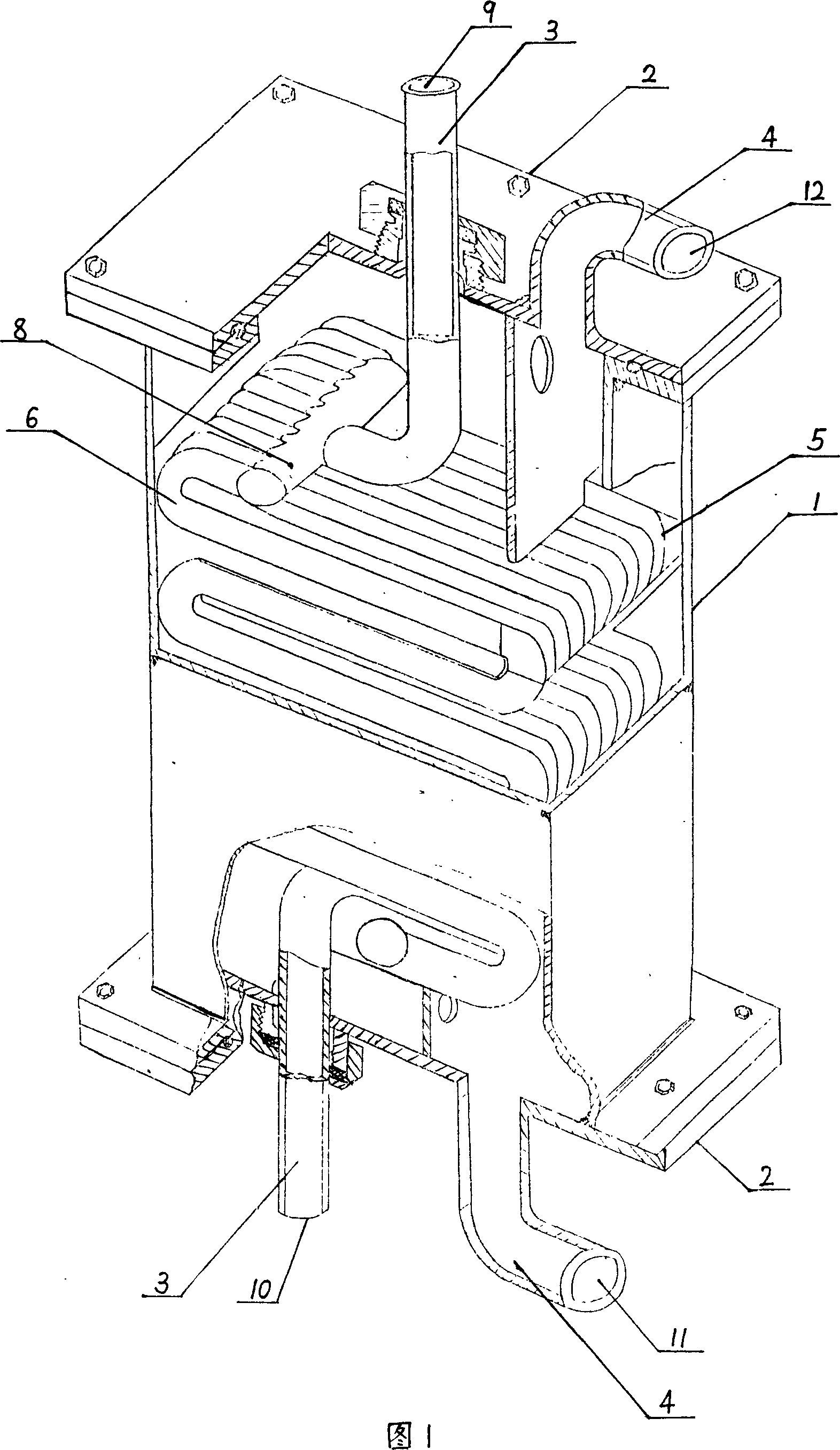
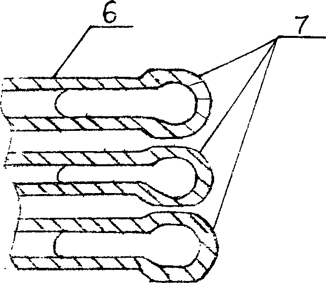
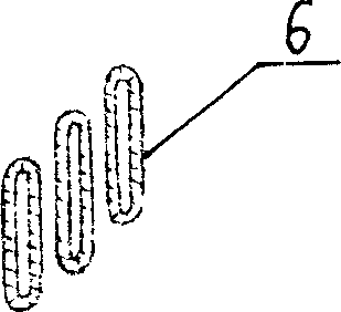
[0011] The new core tube heat exchanger shown in Figure 1 includes a casing 1, an end cover 2, a heat source end tube 3 and a heat exchange tube 4 are respectively arranged on the end cover 2, and a closed body composed of the casing 1 and the end cover 2 is arranged. The heat source core tube 5 is composed of flat tubes 6 arranged in parallel at a certain interval, the heat source core tube 5 communicates with the heat source end tube 3, and the heat exchange tube 4 communicates with the gap between the heat source core tube 5, forming the flat tube of the heat source core tube 5 6 is welded by more than one U-shaped hollow flat tube and the longitudinal section of the end is semicircular. The heat source core tube 5 is connected to the summary tube 8 at the end 7 of the flat tube 6 forming the heat source core tube 5 and the heat source end tube 3 connected.
[0012] The heat source fluid is injected from the heat source end pipe inlet 9, flows through the heat source end pi...
PUM
 Abstract
Description
Claims
Application Information