Apparatus for enlarging tube used in heat exchanger

A technology of heat exchanger tubes and heat exchangers, which is applied in the directions of heat exchange equipment, tubular elements, lighting and heating equipment, etc., can solve the problems of deterioration of transportation efficiency and increase of manufacturing cost, so as to improve transportation efficiency, improve productivity, prevent The effect of rail bending

Inactive Publication Date: 2005-02-09
KYOSHIN KOGYO CO LTD
View PDF0 Cites 6 Cited by
  • Summary
  • Abstract
  • Description
  • Claims
  • Application Information

AI Technical Summary

Problems solved by technology

[0016] Therefore, it is necessary to form a structure in which the guide rod 58 completely blocks the left and right sides of the base portion 50. Furthermore, various hydraulic units and control panels (not shown) are usually arranged on the rear side of the pipe diameter expanding device. Therefore, it is necessary to create a structure in which the heat exchanger can only be carried in and out from the front of the base portion 50 (arrow P) of the diameter expanding device during diameter expansion.
[0017] In this way, when building a heat exchanger production line that should improve production efficiency, when the heat exchanger is moved to the diameter expanding device, or when the heat exchanger is transported from the diameter expanding device to other places and devices, although it is necessary to be on the left and right sides of the diameter expanding device direction (arrow Q), but due to the above reasons, a returning part (reciprocating conveying route) is generated on the conveying route of the production line. Various problems such as increased manufacturing cost of the device itself

Method used


Image

  • Apparatus for enlarging tube used in heat exchanger
  • Apparatus for enlarging tube used in heat exchanger
  • Apparatus for enlarging tube used in heat exchanger

Examples


Embodiment Construction

[0035] In order to explain the present invention in more detail, reference is made to the accompanying drawings.

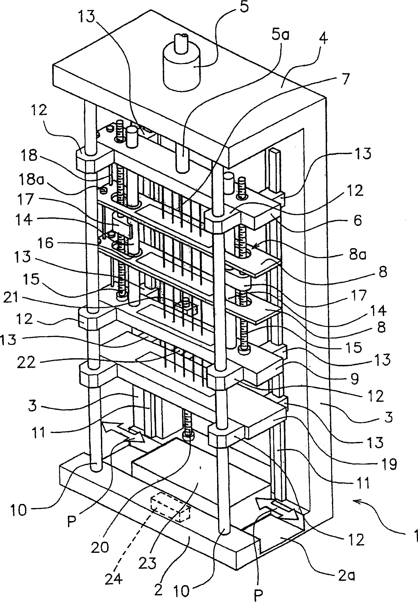
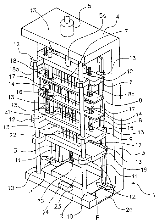
[0036] figure 1 Indicates the overall structure of the expanding device. The top 4 is erected across the upper ends of a pair of pillars 3 standing upward from the rear left and right positions of the base part 2 , and the device frame 1 is constituted by the base part 2 , the pillars 3 and the top 4 .

[0037] Further, a cylinder 5 having a cylinder rod 5 a that expands and contracts from the back of the top 4 toward the base 2 is attached to the top 4 .

[0038] The front end of the above-mentioned cylinder rod 5a is fixedly connected to the central part of the rectangular operating plate 6, and the operating plate 6 can be freely raised and lowered by the expansion and contraction of the cylinder rod 5a of the working cylinder 5.

[0039] In addition, a plurality of mandrels 7 for pipe expansion are vertically provided below the operation plate 6 , and the m...


PUM


Abstract

A tube expander for heat exchangers is capable of organizing an ideal production line where the transportation efficiency is increased and the productivity is improved by having a transportation path in a straight line, that is, applying a method where the heat exchangers are carried into one end of the tube expander (in the left and right direction) and carried out from the opposite end, that is, the other end (so called through-the-center method). The left and right ends of the end plate (9) at the front side are inserted by a pair of first guide bars (10), and the left and right ends at the back side are inserted by a pair of second guide bars (11). A guide path (2a) a for a carrying device (24) or a guide path (2) a to install a transportation device, in either case, the heat exchangers are transported from one end to the other of the base (2), is established on the base (2) that supports the first guide bars (10) and the second guide bars (11) in a clearance between the first guide bars (10) and the second guide bars (11).

Description

technical field [0001] The present invention relates to the expansion of a heat exchanger tube capable of manufacturing a heat exchanger by pressing a tube expanding mandrel for expanding the tube diameter into the tube, and integrating multi-layered cooling fins with a plurality of tubes passing through the cooling fins. diameter device. Background technique [0002] Now, the general structure of the expansion device of the tube for the heat exchanger, for example figure 2 As shown, a top 52 is erected across the upper ends of a pair of pillars 51, 51 provided on the base portion 50, and a working cylinder 53 is installed on the top 52 at the same time. A plurality of mandrels 55 for pipe expansion are arranged on the plate 54 . [0003] Because the above-mentioned tube expansion mandrel 55 is to be suitable for the pipe diameter and tube length of the heat exchanger (not shown) positioned on the base portion 50 and is formed with a rod body with a small diameter and long...

Claims


Application Information

Patent Timeline
Patent Type & Authority Applications(China)
IPC IPC(8): F28F1/32B21D39/20B21D53/08
CPCB21D53/085Y10T29/53122Y10T29/53117B21D39/20
Inventor 户仓谦治
Owner KYOSHIN KOGYO CO LTD
Why Eureka
Try Eureka