Forming die for component of die body

A technology for forming molds and mold shell components, which is applied to mold shells/templates/work frames, building components, ceramic molding cores, etc., and can solve the problems of thin-walled boxes being easily damaged and inconvenient to demold

Inactive Publication Date: 2005-08-31
湖南邱则有专利战略策划有限公司
View PDF2 Cites 2 Cited by
  • Summary
  • Abstract
  • Description
  • Claims
  • Application Information

AI Technical Summary

Problems solved by technology

Such as the positive mold, as can be seen from their drawings, it includes a side mold surface and a lower mold surface (or a top mold surface), and the side mold surface and the lower mold surface form a male mold, which is the male mold

Method used


Image

  • Forming die for component of die body
  • Forming die for component of die body
  • Forming die for component of die body

Examples


Embodiment Construction

[0060] The present invention will be further described below in conjunction with the accompanying drawings and embodiments.

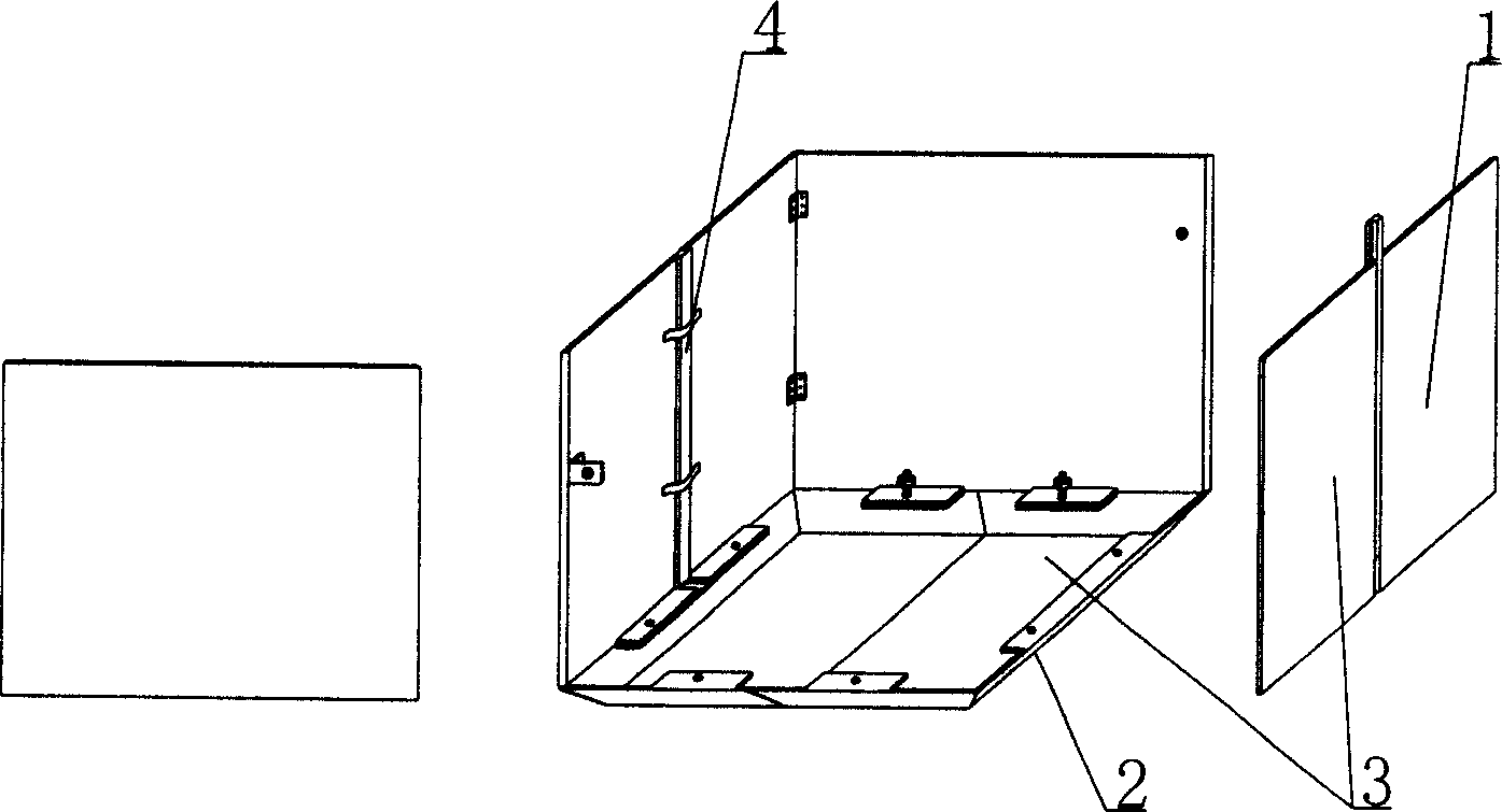
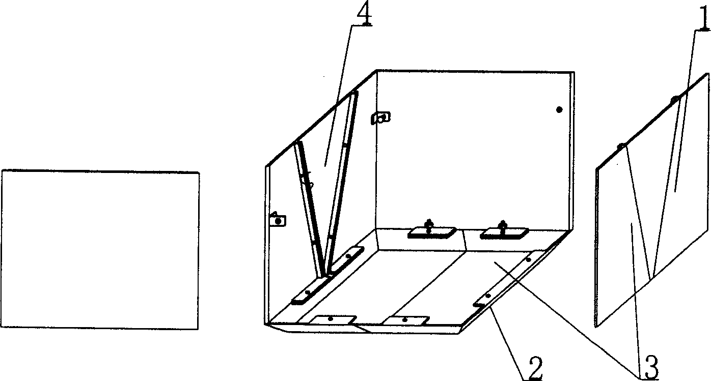
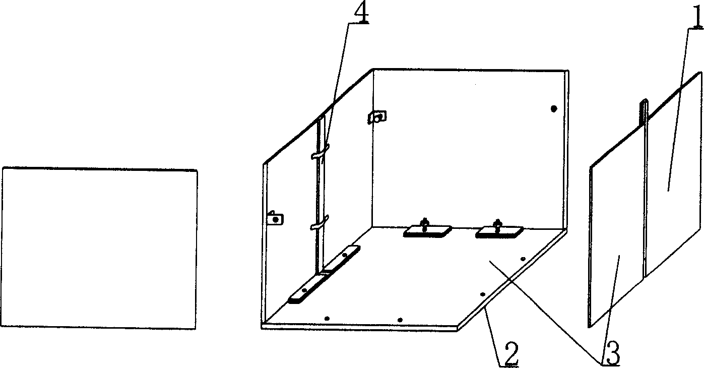
[0061] As shown in the accompanying drawings, the present invention includes a side mold surface 1 and a lower mold surface 2, and the side mold surface 1 and the lower mold surface 2 form a male mold, and is characterized in that the side mold surface 1 and the lower mold surface of the male mold 2 is composed of a template 3, the male mold is composed of at least two templates 3 assembled, and at least one structure or device 4 for extracting and demoulding the template is provided on the assembled template 3. figure 1 It is a structural schematic diagram of Embodiment 1 of the present invention. Among the accompanying drawings, 1 is the side mold surface, 2 is the lower mold surface, 3 is the template, and 4 is the structure or device 4 for extracting and demoulding. In the following accompanying drawings, those with the same numbering have the same ...


PUM


Abstract

A die for forming die shell component uses side die surface and bottom die surface to set up formpiston. It is featured as piecing at least two templates being used as side die surface and bottom die surface together to form the formpiston, setting the piecing device and device for drawing out template on the template for easy and convenient demould in order to use the die to prepare thin wall pipe or box and to prepare thin wall pipe or box with opening.

Description

(1) Technical field [0001] The invention relates to a mold for forming a mold shell component. (2) Background technology [0002] At present, cast-in-place reinforced concrete hollow slabs, especially the non-core-pulling hole-forming process of cast-in-situ reinforced concrete hollow slabs, are generally filled with thin-walled tubes or thin-walled boxes, which can meet the needs of various hollow slabs for evacuating concrete. The applicant applied for an invention patent with the application number 99115665.X and the title "fiber-reinforced thin-walled pipe (box) for reinforced concrete filling and its manufacturing method" on November 29, 1999, and the application number 99115666.8 , the invention patent titled "fiber-reinforced thin-walled box for filling cast-in-place reinforced concrete and its manufacturing method", the thin-walled tube or thin-walled box can be open, and if it has a seal, it can be closed A thin-walled tube or a closed thin-walled box; the mold use...

Claims


Application Information

Patent Timeline
IPC IPC(8): B28B7/28E04B5/16E04G15/00
Inventor 邱则有
Owner 湖南邱则有专利战略策划有限公司
Why Eureka
Try Eureka