

Vehicle safety device
A safety device and vehicle technology, which is applied in vehicle safety arrangement, pedestrian/occupant safety arrangement, vehicle components, etc., can solve the problems of safety device limitation, rising safety device cost, and complex safety device structure, and achieves the effect of ensuring vision
- Summary
- Abstract
- Description
- Claims
- Application Information
AI Technical Summary
Problems solved by technology
Method used
Image

Examples
Embodiment Construction
[0047] Hereinafter, the vehicle safety device according to the first embodiment of the present invention will be described in detail with reference to the drawings.
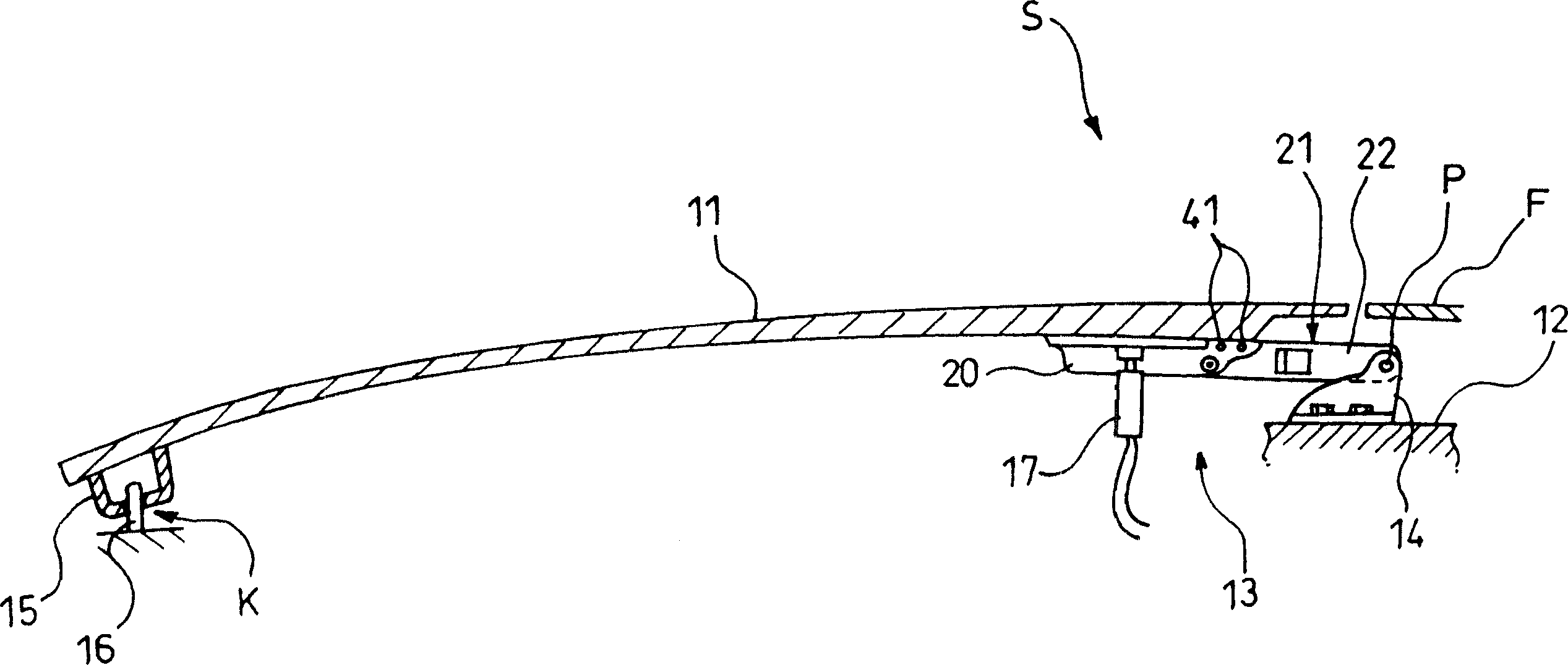
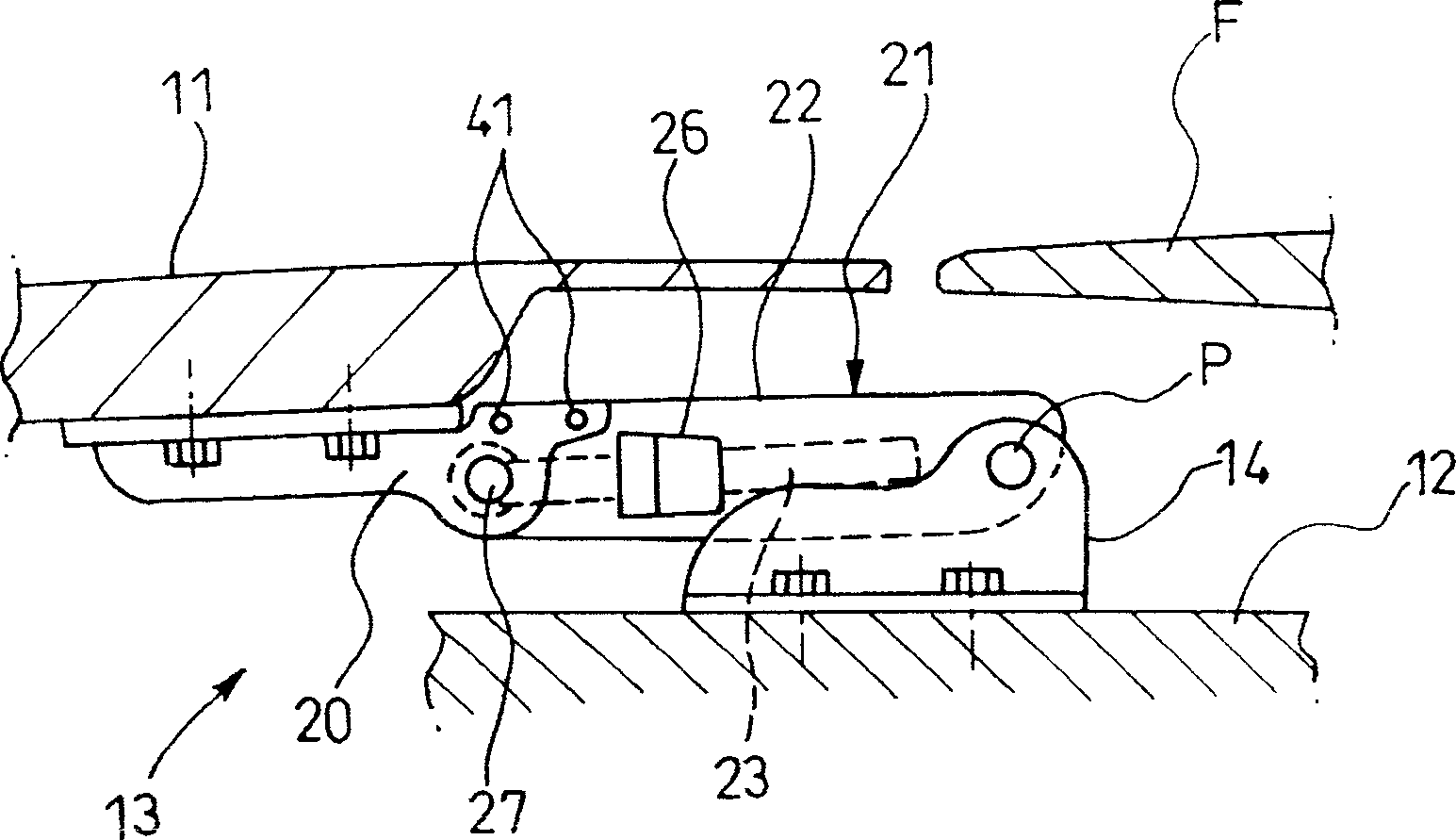
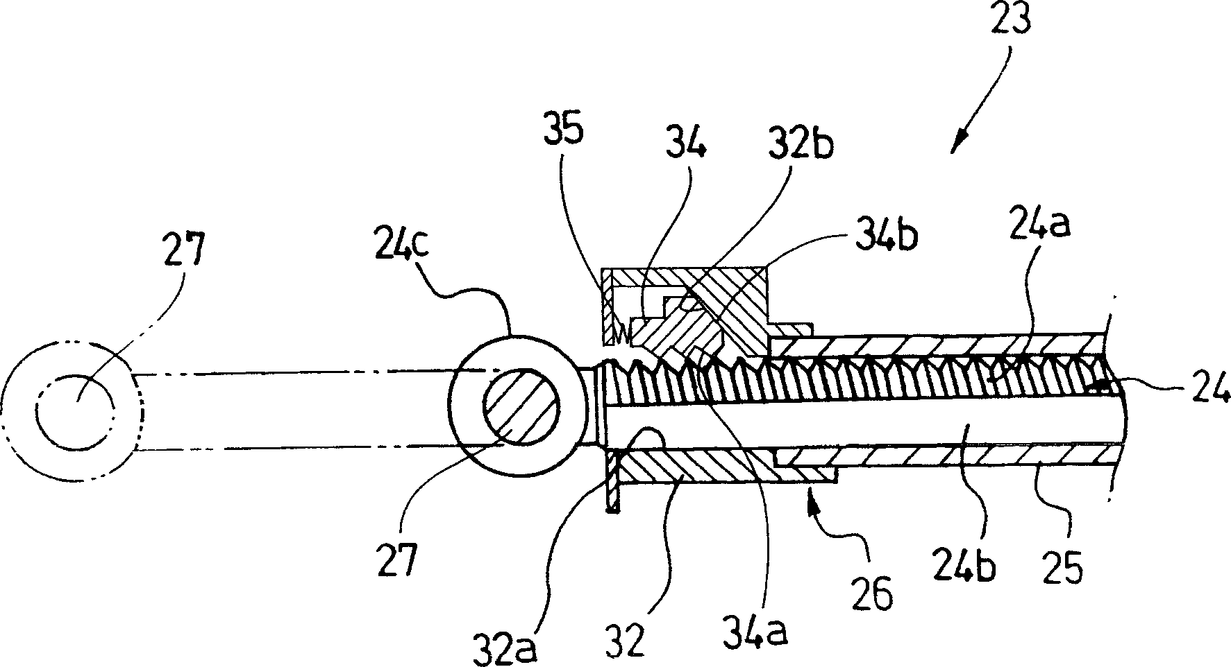
[0048] figure 1 It is a side view of the hood part of the vehicle using the vehicle safety device according to the first embodiment of the present invention, figure 2 is a side view of the aforementioned safety device for a vehicle, image 3 is a cross-sectional view of a locking mechanism of the above safety device for a vehicle, Figure 4 and Figure 5 is a cross-sectional view illustrating the operation of the above locking mechanism, Figure 6 is a cross-sectional view showing the joint structure of the fixing bracket and the supporting bracket of the safety device for a vehicle, Figure 7 It is a side view explaining the opening and closing operation of the engine hood.
[0049] Such as figure 1 As shown, at the front of the vehicle S, a hood 11 covering the upper part of the engine room is provided...
PUM
 Abstract
Description
Claims
Application Information