

Cutter
A technology of blades and cutter heads, which is applied in the field of cutter heads, cutter heads, and knives, and can solve the problem that the connection between blades and cutter heads is not always safe.
- Summary
- Abstract
- Description
- Claims
- Application Information
AI Technical Summary
Problems solved by technology
Method used
Image

Examples
Embodiment Construction
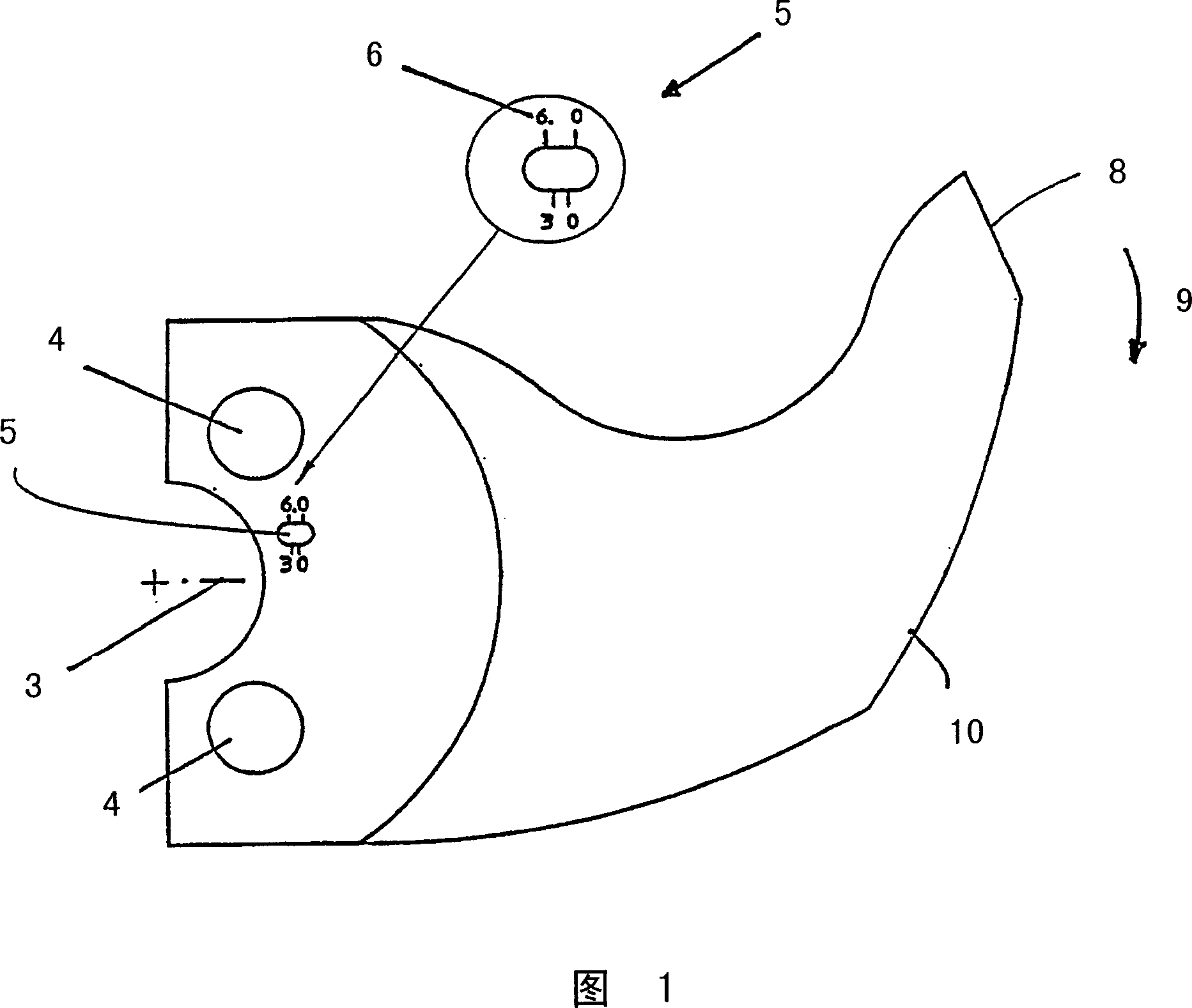
[0021] The blade of the invention is denoted by 8 in FIG. 1 , which rotates in a knife (not shown) in the direction indicated by the arrow represented by reference numeral 9 . The blade thus has a cutting edge 10 on its lower radius. The blades are positioned on the cutter head disc through two holes 4 . According to the invention, the blade has a longitudinal hole 5 arranged offset from the central axis of the blade 8 . The longitudinal hole 5 has an index with which the position of the blade relative to the disc can be identified, as will be explained in more detail with reference to FIGS. 2 and 3 .
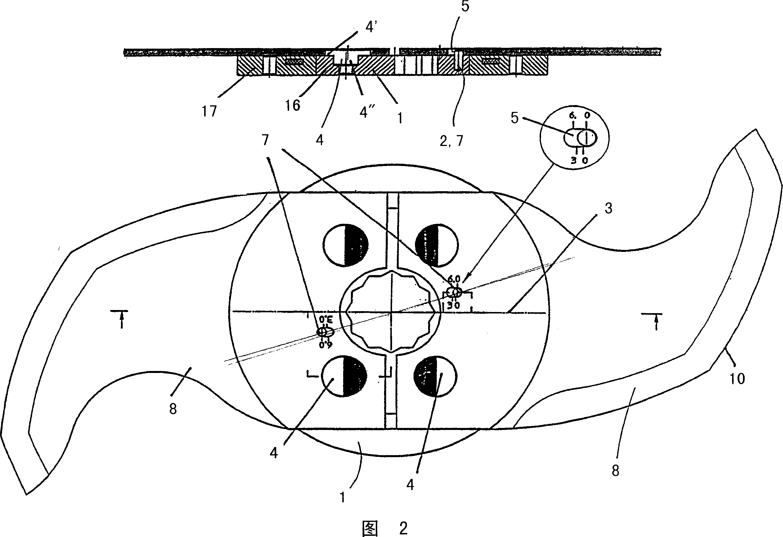
[0022] FIG. 2 shows two blades 8 arranged on the cutter head disc 1 . The cutter head disc 1 has four cutouts or holes, each of them for an eccentric retaining pin 4, by means of which the blade 8 is positioned in the cutter head disc 1 . The eccentric retaining pin 4 has a disc-shaped head 4' which is arranged eccentrically with respect to its base 4", whereby the area mark...
PUM
 Abstract
Description
Claims
Application Information