

Pedicle screw
A technology of screws and implants, applied in the field of implanted screws, can solve problems such as increasing costs
- Summary
- Abstract
- Description
- Claims
- Application Information
AI Technical Summary
Problems solved by technology
Method used
Image

Examples
Embodiment Construction
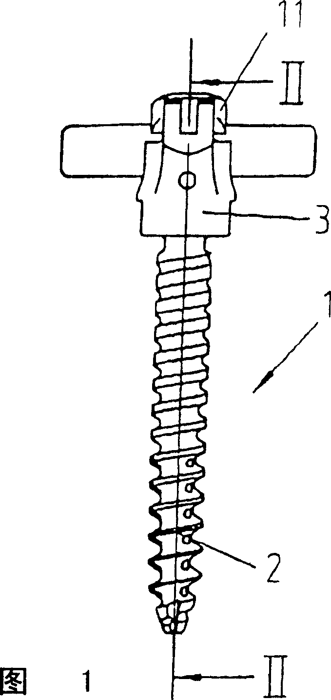
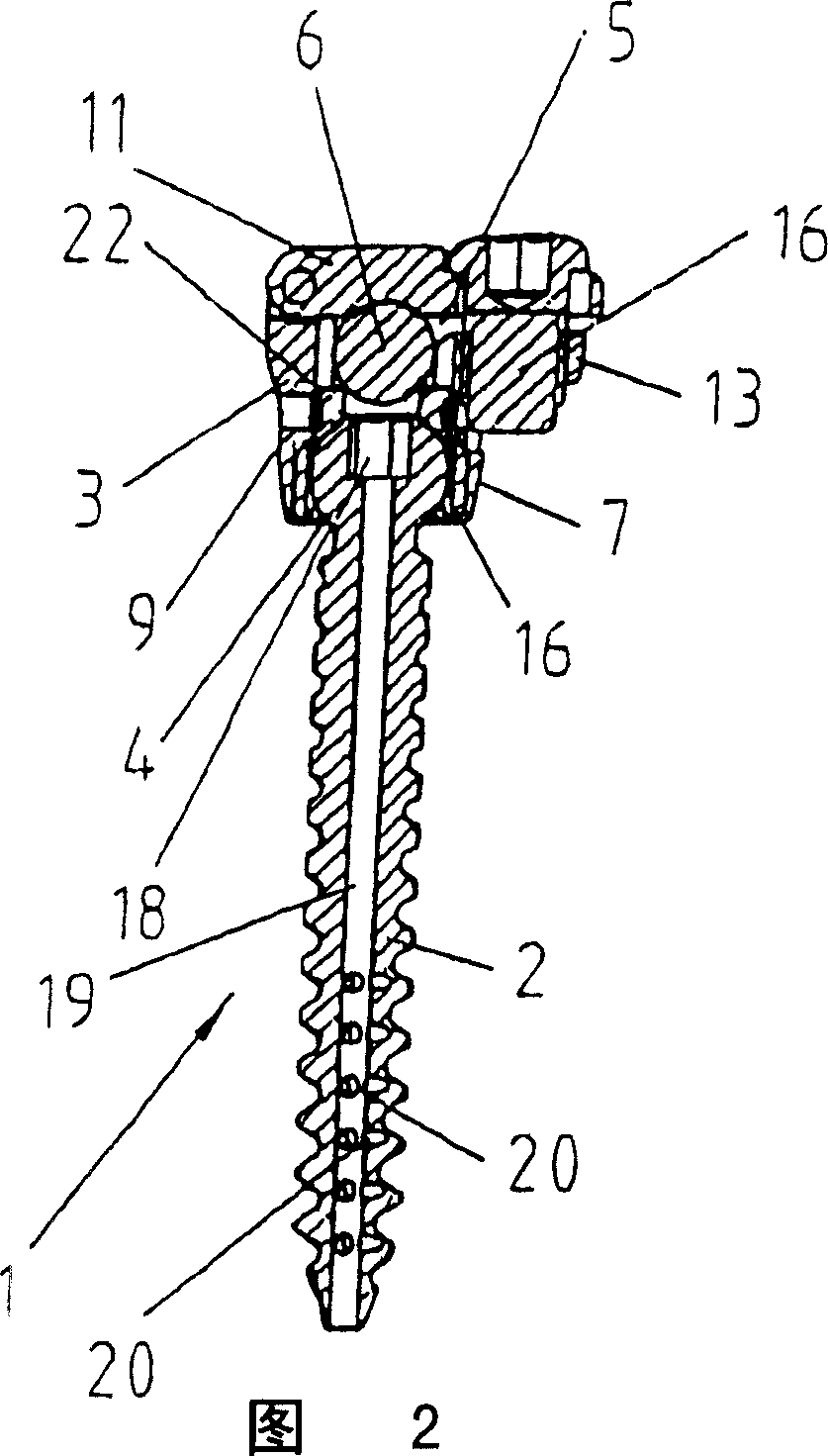
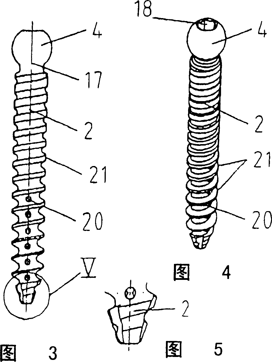
[0042] The drawing shows an implant screw 1 for implants, which consists of a screw shaft 2 and a clip part 3 . On the axial end of the screw 3 is formed a head part 4 which is shaped as a ball head. The clamp part 3 has a clamp receptacle 5 for fastening the connecting rod 6 on the end part 4 , a threaded hole 8 being formed in the clamp base 7 of the clamp part 3 . Furthermore, the clip part 3 has two side legs, wherein a cover 11 is attached to the first side leg 9 via a hinge 10 and projects radially outward from the second side leg 12 laterally away from the first side leg 9 A side leg tongue 13 in which a tongue threaded hole 14 is formed for accommodating a safety bolt 16 passing through the opening 15 of the cover 11 .
[0043] Attach a thread for the end part 4, that is, on the outer surface of the thread ring 26, a ball socket for the ball head of the end part 4 is formed inside the ring, wherein the inside of the ring can be formed by an inner cone or a hemisphere ...
PUM
 Abstract
Description
Claims
Application Information