

Electric discharge machine with rotary table
a rotary table and electric discharge technology, applied in the direction of electrical-based machining apparatus, metal-working apparatus, manufacturing tools, etc., can solve the problems of inevitably large axial dimension of the device, difficult to construct a compact, lightweight rotary table,
- Summary
- Abstract
- Description
- Claims
- Application Information
AI Technical Summary
Benefits of technology
Problems solved by technology
Method used
Image

Examples
Embodiment Construction
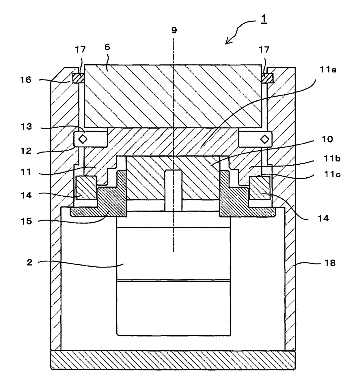
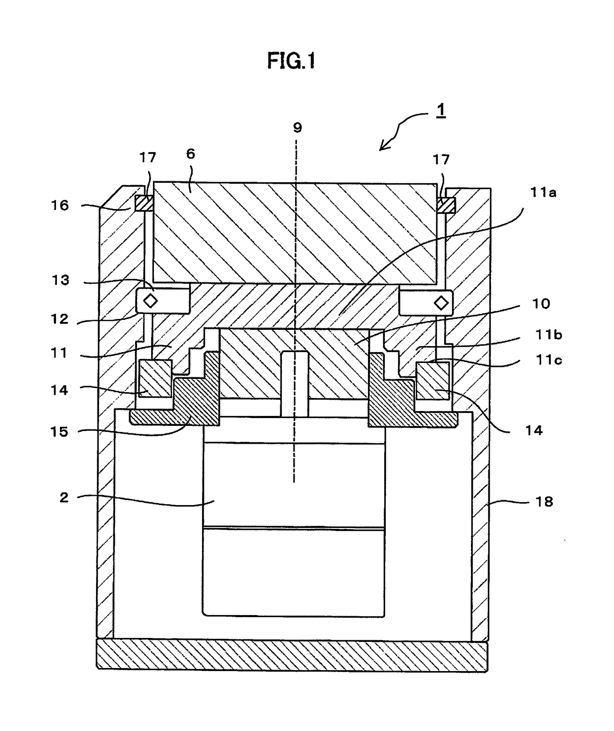
[0023]A first example of a rotary table of an electric discharge machine according to the present invention will first be described with reference to FIG. 1.
[0024]A housing 18 of a rotary table 1 accommodates a power unit 2, speed reducer 10, fixing member 15, shaft 11, bearing 13, face plate 6, and rotation detector 14.
[0025]The face plate 6 serves to fix a workpiece or a jig to which the workpiece is secured. To prevent a machining fluid or the like from getting into the housing 18, a sealing mechanism 16 formed of a seal member 17 is disposed in a gap between the housing 18 and the face plate 6. The power unit 2 comprises, for example, an electric motor. The fixing member 15 is secured to the housing 18, and the power unit 2 and the speed reducer 10 are attached to the fixing member 15.
[0026]The speed reducer 10 is connected to the power unit 2 and the speed-reduction side of the speed reducer 10 is connected to the shaft 11. Further, the face plate 6 is secured to the shaft 11. ...
PUM
| Property | Measurement | Unit |
|---|---|---|
| driving force | aaaaa | aaaaa |
| rotational speed | aaaaa | aaaaa |
| L shape | aaaaa | aaaaa |
Abstract
Description
Claims
Application Information