Unlock instant, AI-driven research and patent intelligence for your innovation.
Full-spectrum covering ultra wideband all photonics-based radar system
What is Al technical title?
Al technical title is built by PatSnap Al team. It summarizes the technical point description of the patent document.
a radar system and full-spectrum technology, applied in the field of microwave optics and radar, can solve the problems of comparatively high precision, transmission and receiving techniques are very difficult to implement for a short pulse signal, and the radar system may only work properly under pre-designed bandwidths, etc., to achieve high detection precision, low jitter, and high coherence
Active Publication Date: 2020-03-31
SHANGHAI JIAOTONG UNIV
View PDF7 Cites 1 Cited by
Summary
Abstract
Description
Claims
Application Information
AI Technical Summary
This helps you quickly interpret patents by identifying the three key elements:
Problems solved by technology
Method used
Benefits of technology
Benefits of technology
[0006]The present invention provides a full-spectrum covering ultra wideband full-photonics based radar system by overcoming the defects of the prior art. The same mode-locked laser with low jitter and wide spectrum is adopted for respectively generating and receiving an ultra wideband chirp signal to guarantee high coherence and high detection precision for the transceiver system. The signal transmitter realizes continuous tunability for center frequency, bandwidth and time width of an ultra wideband signal by making use of the wide spectrum of the mode-locked laser and an unbalanced dispersion chirp on both arms thereof, thus realizing full-spectrum coverage and generation of the ultra wideband signal with any arbitrary operating waveband. The signal receiver greatly mitigates back-end analog-digital converting and processing pressure by making use of time stretching in compressing the center frequency and bandwidth of the wideband signal, with target range resolution still remaining in the accuracy prior to time stretching.
[0013]In the present invention, the mode-locked laser is a mode-locked laser with low jitter and wide spectrum.
[0018]Time stretching of the to be sampled rf signal is equivalent to compression in frequency domain, and thus pressure on bandwidth and sampling ratio for the back-end analog-digital converter is greatly mitigated. Useful target information is then extracted from the analog-digitally converted signal by means of digital processing, with target ranging resolution remaining in the accuracy prior to time stretching.
[0020]1. The signal transmitter and the signal receiver of the present invention are both based on the same mode-locked laser, thus insuring high coherence in signal generation and processing, and drastically increasing ranging detection accuracy for the present invention.
[0022]3. The present invention makes use of time stretching to time stretch the to be sampled signal and compress it in frequency domain, thus drastically mitigating pressure on bandwidth and sampling ratio for the back end analog-digital conversion module.
Problems solved by technology
A radar system, like those in other wireless techniques, may only properly work under pre-designed bandwidths.
Transmission and receiving techniques are very hard to implement for a short pulse signal, due to the extremely stringent requirement for the pulses thereof in high precision ranging, i.e., the requirement for an extremely narrow pulse width.
A phase-coded signal is realized by loading phase information onto a continuous carrier wave according to defined time intervals, albeit has a comparatively high precision and sidelobe suppression ratio, is not suitable for a wideband system, due to the difficult implementation and its susceptibility to Doppler effect and limitation by its own dynamic range.
Method used
Image
Click on the blue label to locate the original text in one second.
Reading with bidirectional positioning of images and text.
Examples
Embodiment Construction
[0032]The present invention will be expounded in more details with the figures and an embodiment hereunder provided. The embodiment is implemented based on the technical solution of the present invention and provided with detailed implementing modes and specific operation procedures, but is not meant to limit the scope of protection of the present invention.
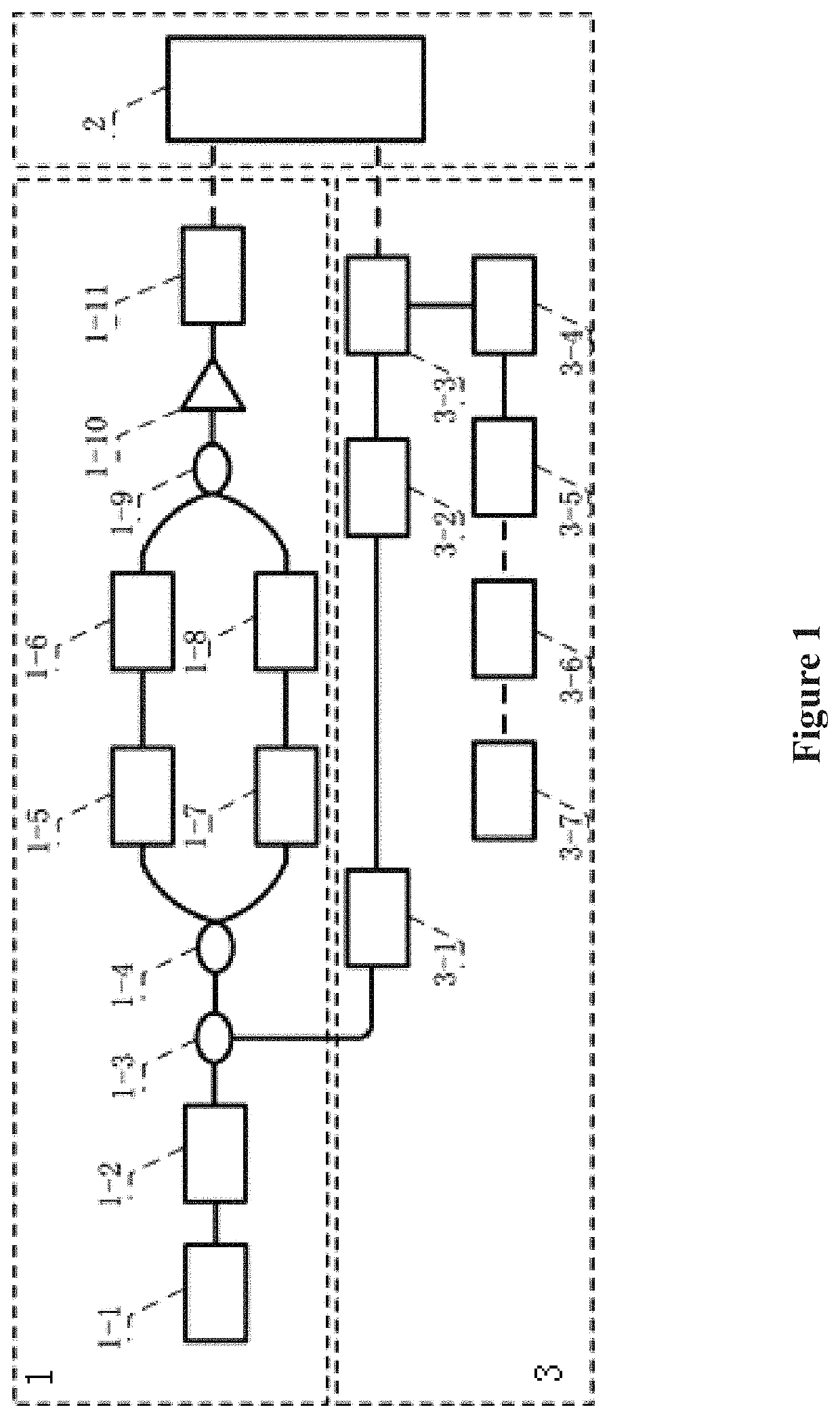
[0033]As shown in FIG. 1, the full-spectrum covering ultra wideband full-photonics based radar system of the present invention comprises a signal transmitter 1, a transceiver module 2, and a signal receiver 3. The signal transmitter comprises a mode-locked laser 1-1, a first dispersion module 1-2, a first optical coupler 1-3, a second optical coupler 1-4, a first optical filter 1-5, a second dispersion module 1-6, a second optical filter 1-7, a first tunable time delay module 1-8, a third optical coupler 1-9, an optical amplifier 1-10, and a first photodetector 1-11.
[0034]The signal receiver comprises 3 a third optical filter 3-1...
PUM
Property
Measurement
Unit
distance
aaaaa
aaaaa
distance
aaaaa
aaaaa
short time Fourier analysis
aaaaa
aaaaa
Abstract
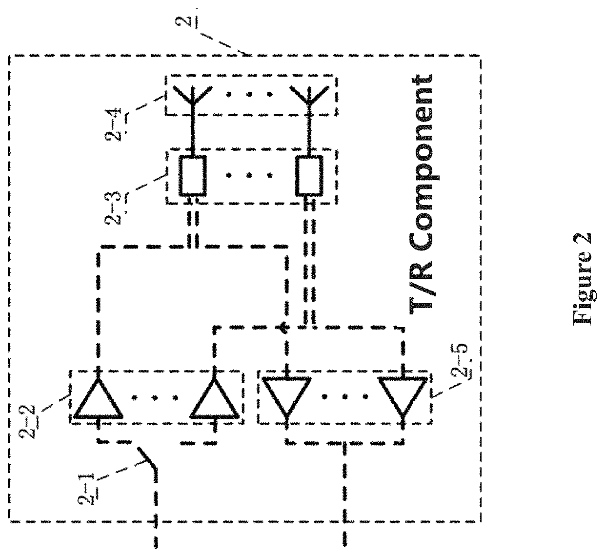
A full-spectrum covering ultra wideband full-photonics based radar system comprising a signal transmitter, a transceiver module, and a signal receiver. The signal transmitter comprises a mode-locked laser, a first dispersion module, a first optical coupler, a second optical coupler, a first optical filter, a second dispersion module, a second optical filter, a first adjustable time delay module, a third optical coupler, an optical amplifier, and a first photodetector; the transceiver module comprises a band selector, a first electrical amplifier array, a T / R component array, an antenna array, and a second electrical amplifier array; the signal receiver comprises a third optical filter, a second adjustable time delay module, an electro-optical modulator, a third dispersion module, a second photodetector, an analog-digital conversion module, and a signal processing module. The system has continuous tunability for center frequency, bandwidth, and time width of the wideband signal with high coherence and ranging accuracy.
Description
CROSS-REFERENCE TO RELATED APPLICATIONS[0001]The subject application is a continuation of PCT / CN2015 / 088463 filed on Aug. 29, 2015 and claims priority on Chinese application no. 201510501404.3 filed on Aug. 17, 2015. The contents and subject matter of the PCT and Chinese priority application are incorporated herein by reference.FIELD OF INVENTION[0002]The present invention relates to microwave optics and radar, particularly, a full-spectrum covering ultra wideband full photonics-based radar system.BACKGROUND ART[0003]As photonics developed since 1980s, the concept of full photonics-based radar has been proposed and attracted wide attention from relevant research at home and abroad. Photonics possesses the advantages of large bandwidth, low loss, and low jitter, with application thereof being capable of breaking the “electronic bottleneck” existing in the traditional microwave / millimeter-wave radar systems, thus furnishing a new technical channel for generation, reception, and proces...
Claims
Application Information
Patent Timeline
Application Date:The date an application was filed.
Publication Date:The date a patent or application was officially published.
First Publication Date:The earliest publication date of a patent with the same application number.
Issue Date:Publication date of the patent grant document.
PCT Entry Date:The Entry date of PCT National Phase.
Estimated Expiry Date:The statutory expiry date of a patent right according to the Patent Law, and it is the longest term of protection that the patent right can achieve without the termination of the patent right due to other reasons(Term extension factor has been taken into account ).
Invalid Date:Actual expiry date is based on effective date or publication date of legal transaction data of invalid patent.

