Separator for fuel cell and fuel cell

a technology of separation device and fuel cell, which is applied in the direction of fuel cell details, electrochemical generators, final product manufacture, etc., can solve the problems of deterioration of mea, difficult to maintain production efficiency, and likely deformation

Active Publication Date: 2022-09-20
TOYOTA JIDOSHA KK
View PDF14 Cites 0 Cited by
  • Summary
  • Abstract
  • Description
  • Claims
  • Application Information

AI Technical Summary

Benefits of technology

[0008]The disclosure provides a separator for a fuel cell and a fuel cell capable of maintaining the production efficiency while the deterioration in a membrane electrode assembly is suppressed.
[0021]According to the aspects, production efficiency can be maintained while the deterioration in the membrane electrode assembly is suppressed.

Problems solved by technology

In the region, the MEA contracts and expands due to repeated drying and wetting, and thus is likely to deform.
Therefore, wrinkles, folds, and the like occur in the MEA, and thus the MEA is deteriorated.
Therefore, it is difficult to maintain the production efficiency.
The problem is not limited to the fuel cell stack mounted in the FCV and is also present in fuel cell stacks for other purposes.

Method used


Image

  • Separator for fuel cell and fuel cell
  • Separator for fuel cell and fuel cell
  • Separator for fuel cell and fuel cell

Examples


first embodiment

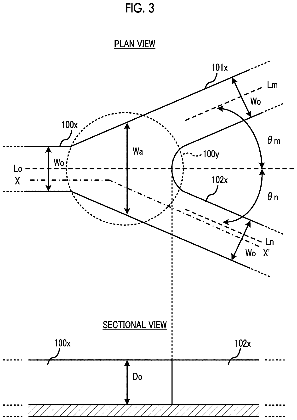
[0066]FIG. 4 is a plan view and a sectional view illustrating the branch portion 10a of a first embodiment. At the branch portion 10a, a single first flow path groove 100 is branched off into two second flow path grooves 101, 102. The angles θm, θn between the directions Lm, Ln in which the second flow path grooves 101, 102 as branch destinations extend and the direction Lo in which the first flow path groove 100 as a branch source extends are equal to each other. In FIG. 4, the section is taken along the line segment Xa-Xb along the flow path grooves 100, 102.

[0067]A narrow portion 101a is provided at the entrance of the second flow path groove 101 as the branch destination, and a narrow portion 102a is provided at the entrance of the second flow path groove 102 as the branch destination. A groove width Wm of the narrow portion 101a and a groove width Wn of the narrow portion 102a are narrower than the groove width Wo of the other portions. The entrance of the second flow path groo...

second embodiment

[0076]FIG. 5 is a plan view illustrating the branch portion 10a of a second embodiment. In FIG. 5, like configurations common to those in FIG. 4 are denoted by like reference numerals, and the description thereof will be omitted. In FIG. 5, the section is taken along the line segment Xa-Xb along the flow path grooves 100, 102.

[0077]The narrow portion 101a is provided at the entrance of the second flow path groove 101 as the branch destination, and the narrow portion 102a is provided at the entrance of the second flow path groove 102 as the branch destination. The narrow portion 100a is also provided at the entrance of the first flow path groove 100 as the branch source. The groove width Wm of the narrow portion 101a, and the groove width Wn of the narrow portion 102a, and a groove width Wk of the narrow portion 100a are narrower than the groove width Wo of the remaining portion. The entrance of the first flow path groove 100 as the branch source indicates a portion of the first flow...

third embodiment

[0082]FIG. 6 is a plan view illustrating the branch portion 10a of a third embodiment. In FIG. 6, like configurations common to those in FIG. 4 are denoted by like reference numerals, and the description thereof will be omitted. In this example, the configuration of the first embodiment is adopted as a base, but the configuration described below can also be applied to the configuration of the second embodiment.

[0083]Two third flow path grooves 81, 82 are adjacent to the first flow path groove 100, the third flow path groove 81 is formed along the flow path grooves 100, 101, and the third flow path groove 82 is formed along the flow path grooves 100, 102. At the narrow portion 101a, the side wall of the second flow path groove 101 protrudes toward the inside of the flow path groove, and the distance between the third flow path groove 81 and the narrow portion 101a is longer than those of the other portions. In addition, at the narrow portion 102a, the side wall of the second flow pat...


PUM

PropertyMeasurementUnit
groove depthaaaaaaaaaa
groove widthaaaaaaaaaa
anglesaaaaaaaaaa

Abstract

A separator for a fuel cell, includes a separator plate provided with a flow path groove group through which the reaction gas flows. The flow path groove group includes a single first flow path groove, a plurality of second flow path grooves, and a branch portion that connects an end portion of the first flow path groove to end portions of the second flow path grooves. The branch portion includes a narrow portion having a narrower groove width than a groove width of a remaining portion of the branch portion. A groove depth of the narrow portion is shallower than a groove depth of the remaining portion of the branch portion.

Description

INCORPORATION BY REFERENCE[0001]The disclosure of Japanese Patent Application No. 2016-239632 filed on Dec. 9, 2016 including the specification, drawings and abstract is incorporated herein by reference in its entirety.BACKGROUND1. Technical Field[0002]The disclosure relates to a separator for a fuel cell and a fuel cell.2. Description of Related Art[0003]Fuel cell vehicles (FCVs) having a fuel cell stack mounted therein have developed as new vehicles different from gasoline vehicles. A fuel cell mounted in the FCV generates power through an electrochemical reaction of a fuel such as hydrogen gas with oxygen in the air, and thus drives a motor.[0004]The fuel cell stack is configured by stacking a plurality of fuel cells. The fuel cell includes a membrane electrode assembly (MEA) in which the electrochemical reaction occurs, and a pair of separator plates with the MEA interposed therebetween. The first separator plate is provided with a flow path groove through which the hydrogen gas...

Claims


Application Information

Patent Timeline
Patent Type & Authority Patents(United States)
IPC IPC(8): H01M8/026H01M8/0254H01M8/0206H01M8/1004
CPCH01M8/026H01M8/0206H01M8/0254H01M8/1004H01M2250/20Y02P70/50H01M8/0258Y02E60/50
Inventor OTSU, WATARUHOSHIKAWA, NAOHIROITO, MASAYUKIKATO, TAKAHIRO
Owner TOYOTA JIDOSHA KK
Why Eureka
Try Eureka