Device to permit offpump beating heart coronary bypass surgery

a technology of coronary bypass and device, which is applied in the field of devices to permit off-pump beating heart coronary bypass surgery, can solve the problems of impaired cardiac performance, irreversible damage to the brain and other tissues and organs of patients, and toxic to older and debilitated patients, so as to achieve the effect of improving cardiac performance and not seriously impairing heart performan

a technology of coronary bypass and device, which is applied in the field of devices to permit off-pump beating heart coronary bypass surgery, can solve the problems of impaired cardiac performance, irreversible damage to the brain and other tissues and organs of patients, and toxic to older and debilitated patients, so as to achieve the effect of improving cardiac performance and not seriously impairing heart performan

US20010041827A1Inactive Publication Date: 2001-11-15MAQUET CARDIOVASCULAR LLC

Image

  • Device to permit offpump beating heart coronary bypass surgery
  • Device to permit offpump beating heart coronary bypass surgery
  • Device to permit offpump beating heart coronary bypass surgery

Examples


Embodiment Construction

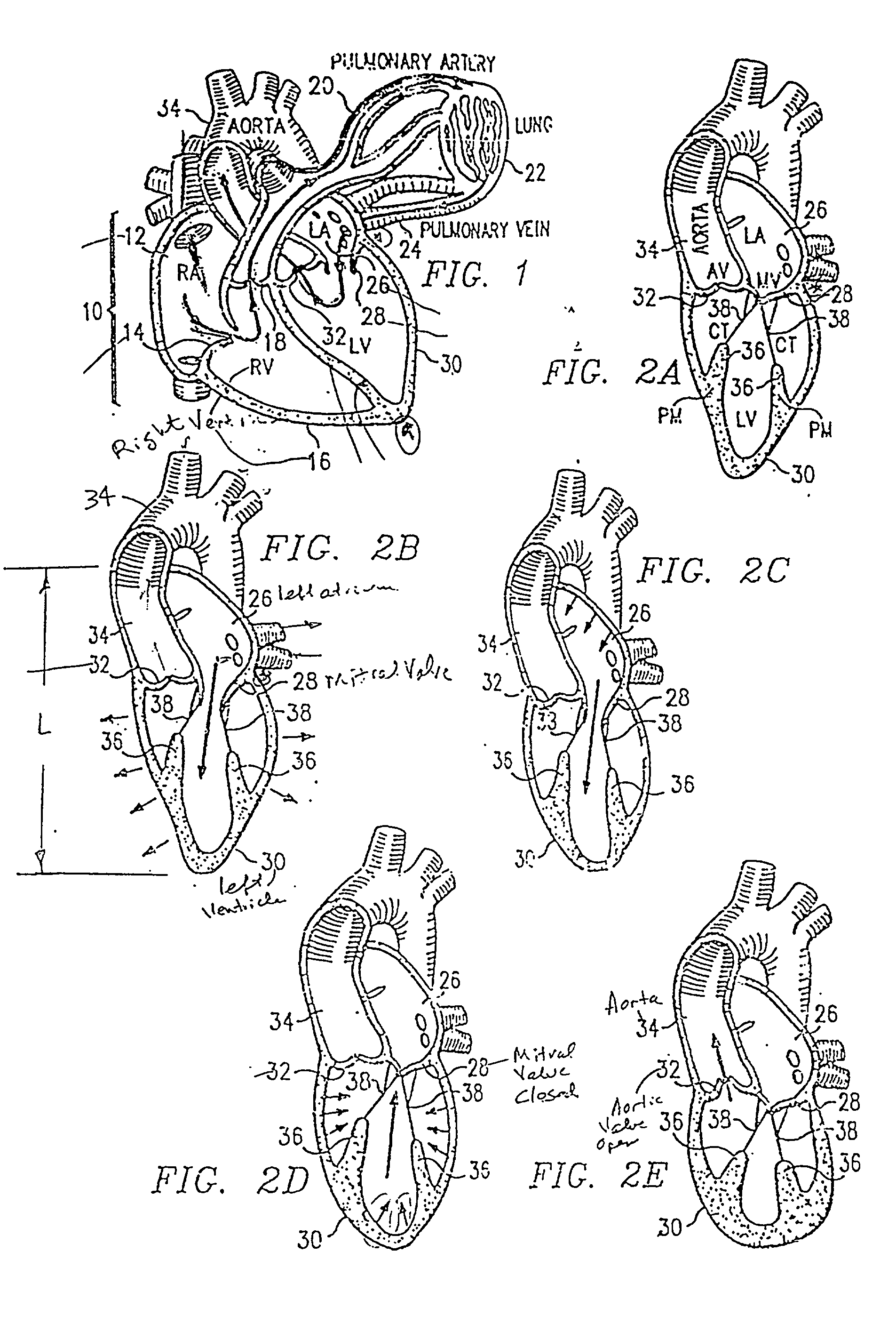
[0093] By way of introduction, the operation of a heart will be discussed before describing the system embodying the present invention. In FIG. 1, the normal circulatory pattern of blood through heart 10 is illustrated. Blood from the venous system enters the first chamber of the heart, the right atrium (R.A.) 12. From right atrium 12, it passes through tricuspid valve 14 into right ventricle (R.V.) 16 via pulmonic valve 18, entering pulmonary artery 20 which leads to lungs 22. In lungs 22, carbon dioxide is released and the blood is reoxygenated. Blood then exits lungs 22 back into pulmonary vein 24 which leads to left atrium (L.A.) 26. From left atrium 26, blood passes through mitral valve 28 into left ventricle (L.V.) 30. Blood then exits heart 10 via aortic valve 32 into aorta 34 and the generalized arterial circulation.

[0094] Cardiac contraction is orchestrated by electrical impulses originating from the heart's nervous system. Electrical stimulation to the myocardial fibers re...


PUM


Abstract

A system for manipulating a heart during cardiac surgery links lifting of the heart and regional immobilization which stops one part of the heart from moving to allow expeditious suturing while permitting other parts of the heart to continue to function whereby coronary surgery can be performed on a beating heart while maintaining cardiac output unabated and uninterrupted. Circumflex coronary artery surgery can be performed using the system for manipulating a heart during cardiac surgery of the present invention. The system is an improvement on the retractor disclosed in parent application Ser. No. 08/936,184 filed on Sep. 17, 1997 and locates a suspension head near the apical region of the heart and a gross support near the base of the heart near the AV groove. A frame is positioned within the patient's thoracic region and moves with the patient, and a surgical target immobilizer can be used to assist in the movement of the heart if desired. A special suction cup is used which accommodates multiplanar movement of the heart and the myocardium while also preventing heart tissue from interrupting the suction being applied to the heart. One form of the system can be used in minimally invasive surgery.

Description


Claims


Application Information

Patent Timeline
15 Nov 2001
Publication
US20010041827A1