

Liquid crystal display device
a display device and liquid crystal technology, applied in static indicating devices, non-linear optics, instruments, etc., can solve the problems of not being able to ignore such a drawback, and the display device cannot provide the clarity or discrimination of motion picture images
- Summary
- Abstract
- Description
- Claims
- Application Information
AI Technical Summary
Benefits of technology
Problems solved by technology
Method used
Image

Examples
embodiment 1
[0177] [Equivalent Circuit of Liquid Crystal Display Device]
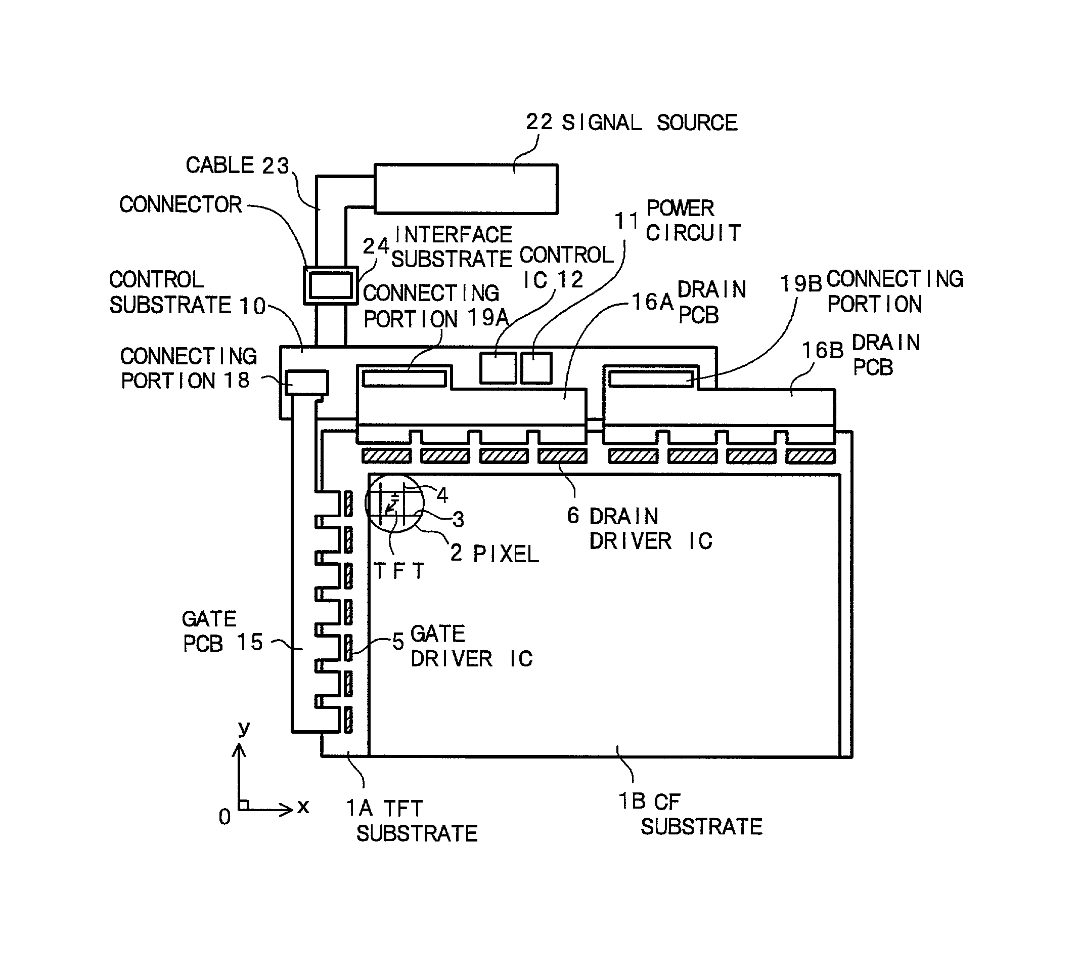
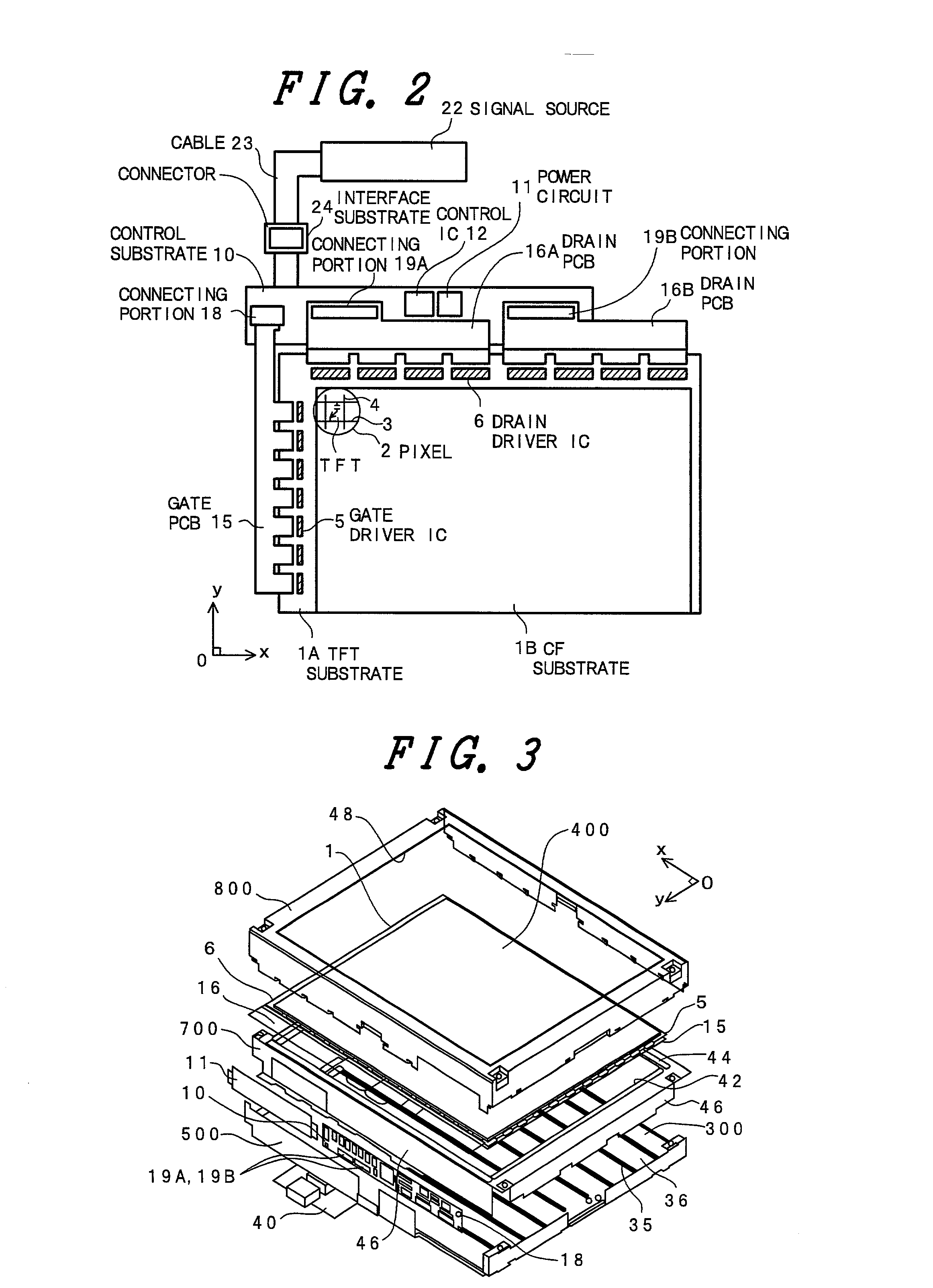
[0178] FIG. 2 is an equivalent circuit diagram showing one embodiment of a liquid crystal display device according to the invention. Although the drawing is a circuit diagram, it is drawn corresponding to an actual geometric arrangement.
[0179] In this embodiment, the present invention is applied to a liquid crystal display device which adopts a so-called lateral electric field type which is known as a type having a wide viewing angle.
[0180] First of all, a liquid crystal display panel 1 is shown in FIG. 2 and this liquid crystal display panel 1 uses transparent substrates 1A, 1B which are arranged to face each other while sandwiching liquid crystal therebetween thus constituting an envelope. In this case, one transparent substrate (a lower-side substrate in the drawing, a matrix substrate 1A) is formed slightly larger than the other transparent substrate (an upper-side substrate in the drawing, a color filter substrate 1B),...
embodiment 2
[0294] The above-mentioned embodiment is characterized by repeating the lighting and the extinguishing of the light sources of the backlight 300 when the image has the movement.
[0295] However, it is needless to say that whether the screen of the display portion is bright or dark is first detected and then the lighting and the extinguishing of the light sources of the backlight 300 may be repeated when the screen is dark.
[0296] It is because that when a scene is displayed on the display portion at night, for example, the screen generally becomes dark so that the recognition of a profile of a subject which moves within the screen becomes difficult. Even in such a case, by repeating the lighting and the extinguishing of the light sources of the backlight 300, the discrimination of the subject can be enhanced.
[0297] In this case, it may be possible to repeat the lighting and the extinguishing of the backlight 300 without increasing the lamp current. It is because that although the scree...
embodiment 3
[0300] FIG. 12 is an explanatory view showing another embodiment of a liquid crystal display device according to the present invention.
[0301] In the drawing, a display surface AR of a liquid crystal display panel 1 is conceptually classified into three regions consisting of a center region AR.sub.0 and respective regions AR.sub.1, AR.sub.2 which are disposed above and below the center region AR.sub.0, wherein respective light sources 35 (0) of a backlight 300 which are in charge of the transmission of light at the center region AR.sub.0 are made to repeat the lighting and the extinguishing, while the respective light sources 35 (1), 35 (2) of the backlight 300 which are in charge of the light transmission of light at the upper and lower regions AR.sub.1, AR.sub.2 are made to maintain the lighting.
[0302] The center of the display surface AR constitutes a region where the interest of an observer concentrates and a subject having the movement is usually displayed as an image on this re...
PUM
 Abstract
Description
Claims
Application Information