Switch structure

a technology of switch structure and switch body, which is applied in the direction of emergency actuators, contact mechanisms, tumbler/rocker switch details, etc., can solve the problems of affecting operation, affecting and reducing the operation of the switch

Inactive Publication Date: 2004-01-08
DENSO CORP
View PDF8 Cites 13 Cited by
  • Summary
  • Abstract
  • Description
  • Claims
  • Application Information

AI Technical Summary

Problems solved by technology

However, in the switch structure shown in FIG. 12, as the push rod section P9 and the push button section P5 are separate parts, there is the cost of the part, a die and assembly for each part, resulting in a rise in the manufacturing cost.
Moreover, a problem occurs that a sound of parts returning into place is produced between the push button section P5 and the push rod section P9, resulting in a loss of excellent feel of the switch.
As described above, if the push rod section P9 tilts with respect to the switch element P11 or the tip of the push rod section P9 is offset from the center of the

Method used


Image

  • Switch structure
  • Switch structure
  • Switch structure

Examples


first embodiment

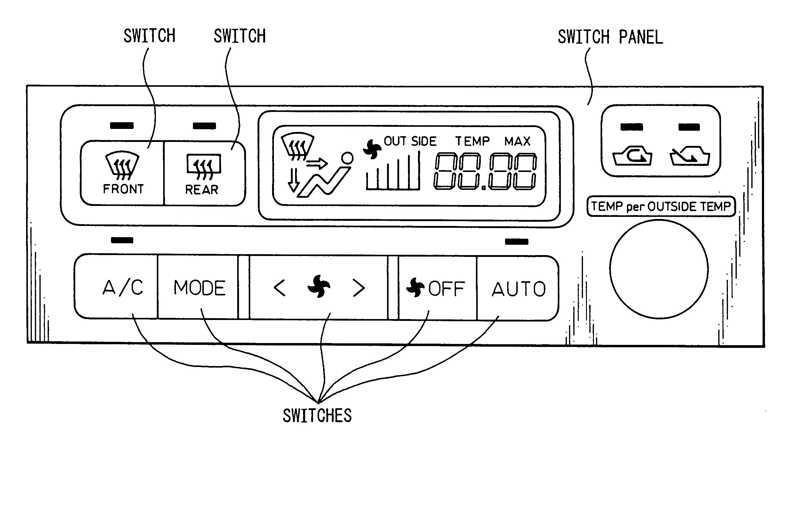
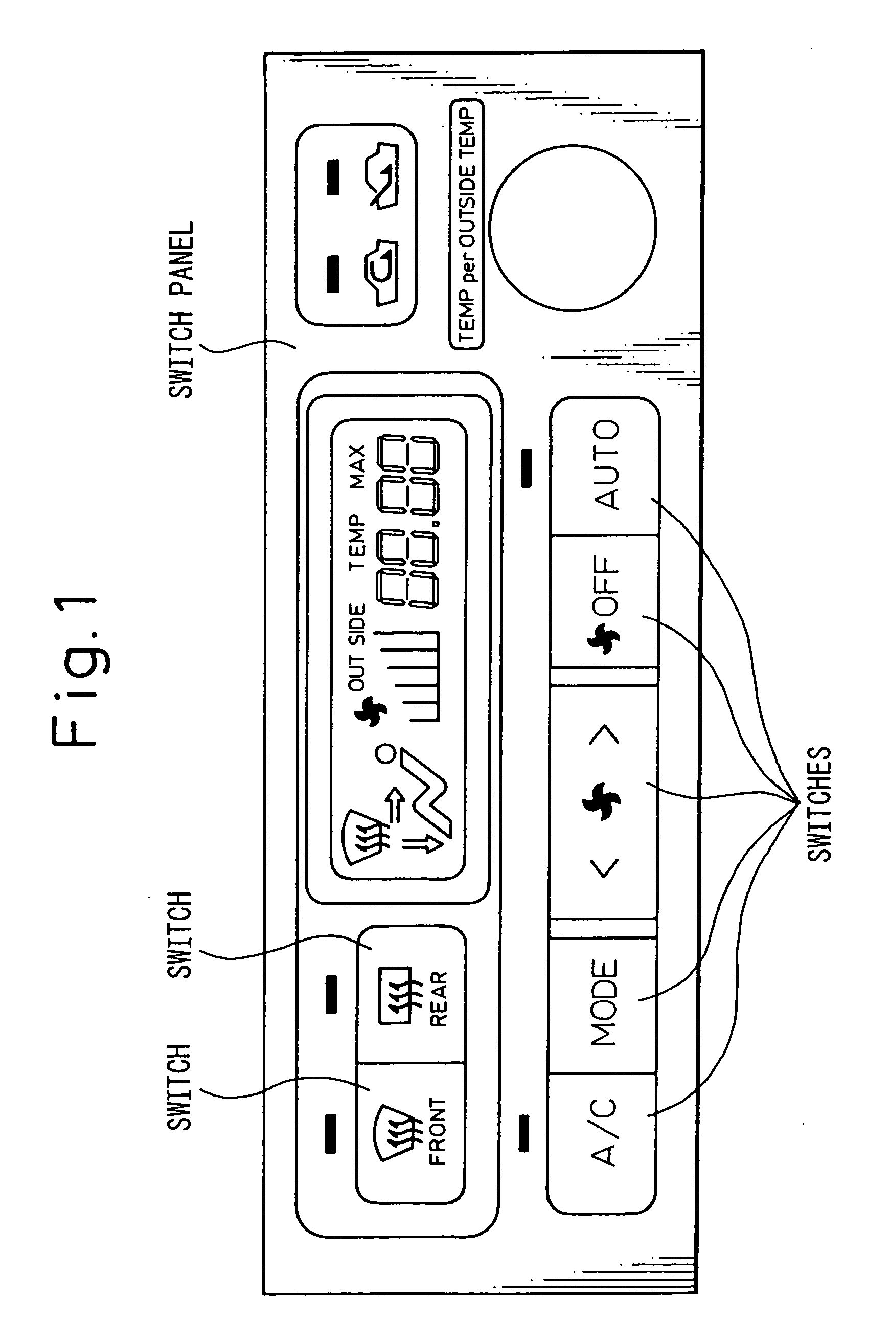
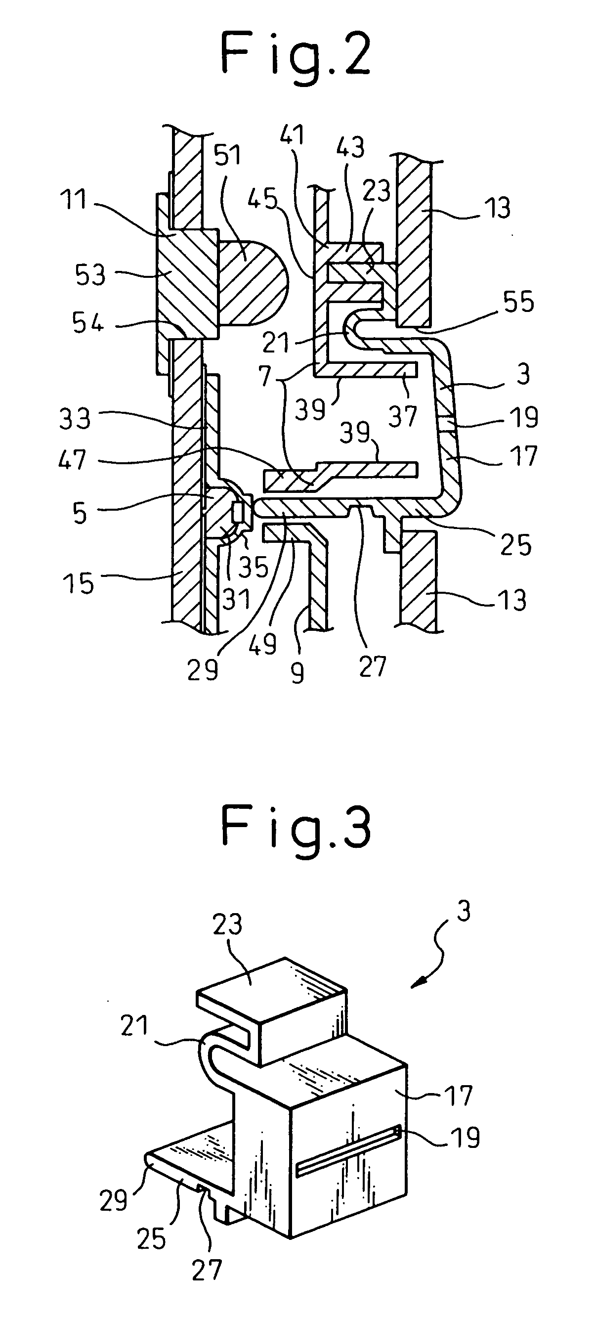
[0052] Next, the embodiments of the switch structure according to the present invention are described below. First, the switch structure in the first embodiment is described by reference to FIG. 1 to FIG. 4. Here, FIG. 1 is an external view of a switch panel of an air conditioner for a vehicle, FIG. 2 is a sectional side elevation of a switch structure, and FIG. 3 and FIG. 4 are perspective views of the parts making up the switch structure.

[0053] The switch structure in the first embodiment is used as a switch panel of an air conditioner for a vehicle shown in FIG. 1. The switch panel comprises a plurality of switches (such as a fan switch) for directing various operations of the air conditioner, and the switch structure in the first embodiment is used in these switches.

[0054] As shown in FIG. 2, the switch structure in the first embodiment comprises a push button section 3 that pivots when pushed, a switch element 5 that is mechanically turned on and off by the push button section ...

second embodiment

[0083] The switch structure in the second embodiment comprises the push button section 3 that pivots when pushed, an internal guide section 57 that guides the movement of the push button section 3, a case 58 that is the body of the switch structure, an upper side switch element 59 (switch element A) and a lower side switch element 61 (switch element B), that is, a pair of switches to be turned on and off by the push button section 3, the light source section 11 that illuminates the push button section 3, and the substrate 15 that supports the upper side switch element 59, the lower side switch element 61 and the light source section 11.

[0084] The push button section 3 has the box-shaped push portion 17. A surface portion 63, which is the front side surface (right-hand side in FIG. 6) of the push portion 17, is formed so that its central area is slightly hollowed and comprises an upper side convex portion 65, which is a convex portion located at the upper side of the surface portion ...

third embodiment

[0106] According to the switch structure in the third embodiment, however, the push button section 3 comprises a pivot shaft 93 above the push portion 17. The supporting member 7 comprises a shaft bearing portion 97 that supports the pivot shaft 93 while allowing a pivot movement. Therefore, when the push portion 17 is pushed, the push button section 3 can pivot about the pivot shaft 93 as a center.

[0107] The switch structure in the third embodiment has the same effects as the switch structure in the first embodiment.


PUM


Abstract

A switch structure comprising a switch element (5, 59, 61) performing circuit switching operation by pushing and a push button section (3) attached rotationally movably to a supporting member (7, 91) and having a push rod section (25, 77, 81) pushing the switch element and integrally formed thereto, wherein a switching operation is performed when the push button section (3) is rotationally moved by pushing and push rod section pushes the switch element, wherein the push rod section is provided with a flexible portion (27) able to bend when pushed, and wherein a guide section (47, 57, 49) is provided which comes into contact with the push rod section to bend the flexible portion and, at the same time, guides the push rod section to push the switch element in the normal direction when the push button section is rotationally moved by pushing.

Description

[0001] 1. Field of the Invention[0002] The present invention relates to a switch structure used in an operation switch panel for an air conditioner, an audio system, and so on, for a vehicle.[0003] 2. Description of the Related Art[0004] Conventionally, a switch structure shown in FIG. 12 is used in an operation switch panel for an air conditioner, an audio system, and so on, for a vehicle.[0005] The switch comprises a push button section P5 attached to a supporting member P1 in such a way that the push button section P5 can pivot around a pivot shaft P3 as a center, a push rod section P9 pushed inward by the push button section P5 while being guided by a guide section P7 when the push button section P5 pivots, and a switch element P11 that is turned on and off by the push rod section P9 pushed inward.[0006] Another switch structure shown in FIG. 13 comprises a push button section P5 formed integrally with the push rod section P9 while being pivotally attached to the supporting memb...

Claims


Application Information

Patent Timeline
IPC IPC(8): H01H21/00H01H13/70H01H21/02H01H23/16
CPCH01H13/70H01H2003/466H01H2221/09H01H2219/062H01H2221/016H01H2219/014H01H21/02
Inventor ITO, MASAHIROYAMAZAKI, YASUHIKO
Owner DENSO CORP
Why Eureka
Try Eureka