Multi-channel head position controlling apparatus and method of controlling position of multi-channel head

a multi-channel head and position control technology, applied in the field of multi-channel, can solve the problems of difficult to realize high-density recording on the tape-like recording medium 9, and difficulty in maintaining accurate servo control

Inactive Publication Date: 2004-06-24
SONY CORP
View PDF13 Cites 22 Cited by
  • Summary
  • Abstract
  • Description
  • Claims
  • Application Information

AI Technical Summary

Problems solved by technology

Then the distance between the tracks on the tape-like recording medium 9 is also changed, with the result that it becomes difficult to accurately align all of the unit recording heads 1 to 5 with the respective track centers CH1 to CH 3.
For this reason, there is a tendency to cause a so called off-track, leading to difficulty in maintaining accurate servo-control.
However, when a lot of effort is requested to accurately align the unit recording heads 1 to 5 with the respective track centers CH1 to CH3, to improve the track density also requires limitless effort, with the result that it becomes difficult to realize high-density recording on the tape-like recording medium 9.

Method used


Image

  • Multi-channel head position controlling apparatus and method of controlling position of multi-channel head
  • Multi-channel head position controlling apparatus and method of controlling position of multi-channel head
  • Multi-channel head position controlling apparatus and method of controlling position of multi-channel head

Examples


Embodiment Construction

[0022] Preferred embodiments of the present invention will be hereinafter described with reference to the attached drawings. In the drawings, similar parts corresponding to those of a conventional arrangement will be attached with the same reference numerals and they will not be described in detail.

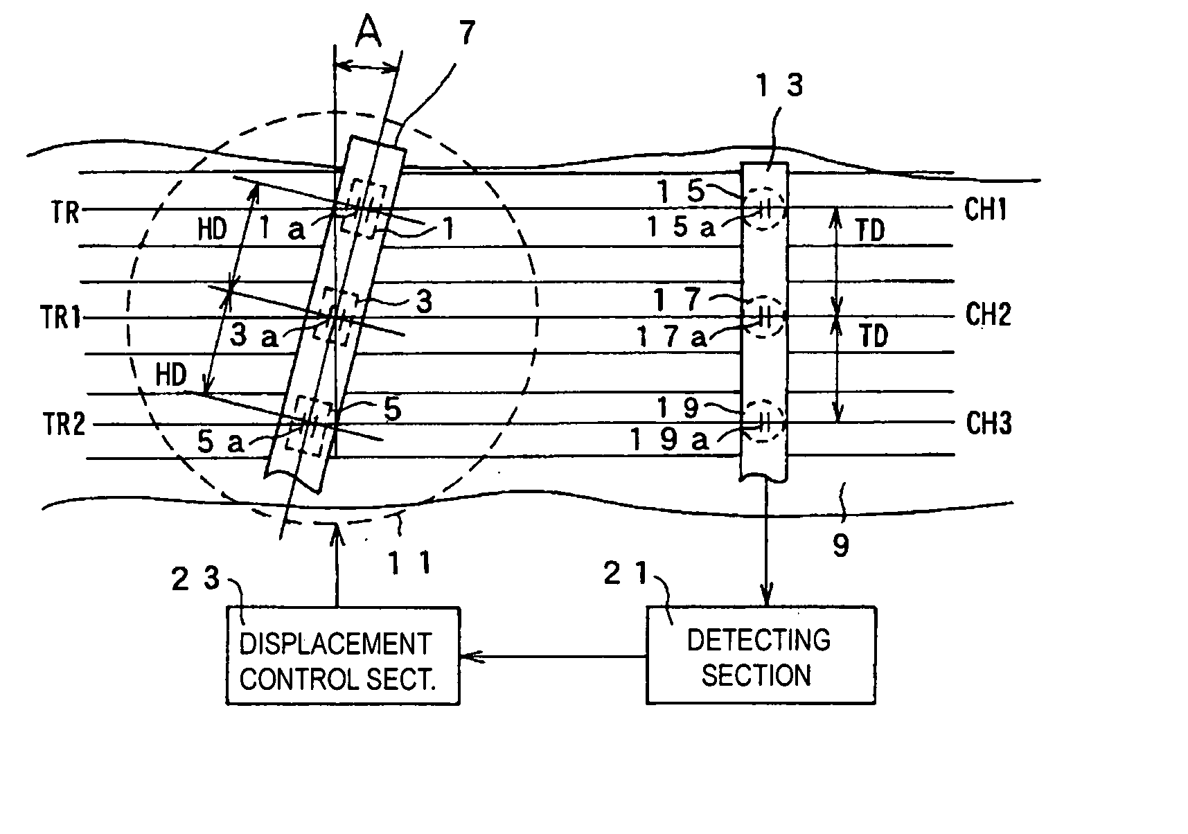
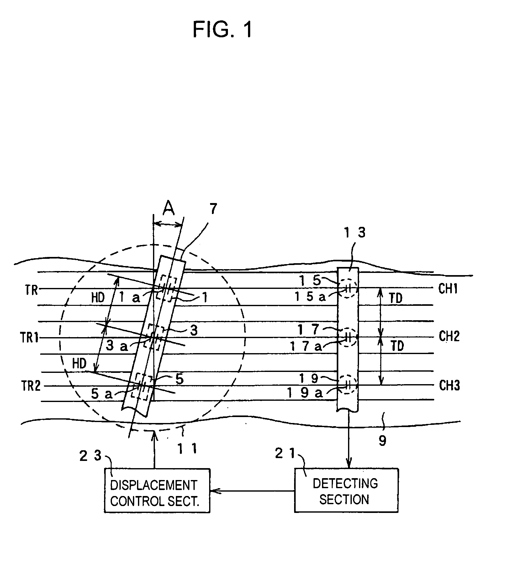
[0023] FIG. 1 is a diagram showing one embodiment of the multi-channel head position controlling apparatus according to the present invention. A method of controlling the position of the multi-channel head will be described together with the description of an operation of the multi-channel head position control apparatus.

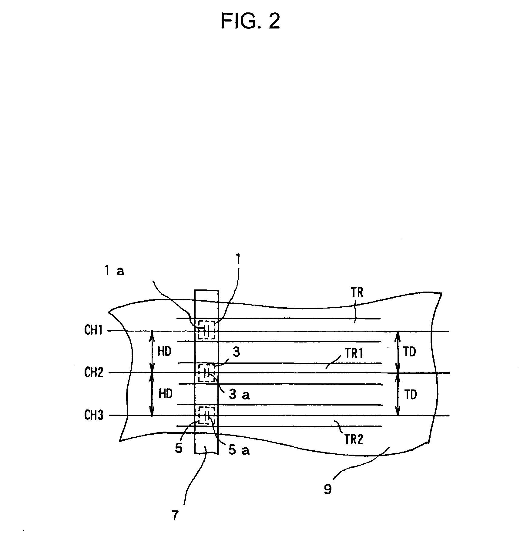
[0024] As shown in FIG. 1, a multi-channel head 7 is a longitudinally elongated block head having unit recording heads 1, 3, 5, integrally formed with the block in which the unit recording heads 1, 3, 5 are arrayed in the longitudinal direction with a predetermined spacing (distance) between the adjacent unit recording heads, for example. As will be described later on, th...


PUM

PropertyMeasurementUnit
azimuth angleaaaaaaaaaa
widthaaaaaaaaaa

Abstract

A multi-channel head position control apparatus and a method of controlling the position of the multi-channel head in which even if the width of a tape-like recording medium is changed, each of unit recording heads constituting a multi-channel head can be aligned with corresponding track centers. The multi-channel head having a plurality of unit recording heads arrayed in the longitudinal direction is disposed so that the alignment direction of the unit recording heads forms an azimuth angle relative to the running direction of the tape-like recording medium. The position of the multi-channel head is controlled by a supporting section in accordance with a control signal recorded on the tape-like recording medium and detected by a detecting section so that the alignment between each of the unit recording heads and corresponding track center is maintained.

Description

[0001] The present document is based on Japanese Priority Application JP2002-193225, filed in the Japanese Patent Office on Jul. 2, 2002, the contents of which being incorporated herein by reference to the extent permitted by law.[0002] 1. Field of the Invention[0003] The present invention relates to a multi-channel head position controlling apparatus and a method of controlling position of the multi-channel head. More particularly, the present invention relates to a multi-channel head position controlling apparatus for use in a magnetic recording apparatus for recording via a multi-channel head, control signals, digital data signals and the like on multi-linear recording tracks of tape-like recording media.[0004] 2. Description of the Related Art[0005] When control signal, digital data signal and the like are recorded on the multi-linear recording tracks of a tape-like recording medium such as a magnetic tape, a conventional multi-channel head structure is utilized such as the one ...

Claims


Application Information

Patent Timeline
Patent Type & Authority Applications(United States)
IPC IPC(8): G11B5/52G11B5/58G11B5/584
CPCG11B5/584G11B5/52
Inventor ITO, HIROKO
Owner SONY CORP
Why Eureka
Try Eureka