Measuring point bolt and method of making the bolt

a technology of measuring point and bolt, which is applied in the direction of screws, mechanical measuring arrangements, instruments, etc., can solve the problems that the known measuring point bolts are no longer able to meet these demands, and achieve the effect of preventing equalization of air pressur

Active Publication Date: 2005-01-13
SFS GRP INT AG
View PDF15 Cites 5 Cited by
  • Summary
  • Abstract
  • Description
  • Claims
  • Application Information

AI Technical Summary

Benefits of technology

[0022] The invention also provides for a measuring-point bolt comprising a one-piece body comprising a flange, a first end projecting from one side of the flange, and a second end projecting from another side of the flange. The first end comprises an internal opening and being adapted to connect to a measuring device. The second end is adapted connect to another measuring device. A main internal opening is arranged within the body and communicating with the internal opening of the first end. An element is movably arranged within the body. The element is structured and arranged to prevent entry of foreign particles into the body. A sealing cap is at least one of non-removably connected to the sec...

Problems solved by technology

However, known measuring-point bolt ...

Method used


Image

  • Measuring point bolt and method of making the bolt
  • Measuring point bolt and method of making the bolt

Examples


Embodiment Construction

[0032] The particulars shown herein are by way of example and for purposes of illustrative discussion of the embodiments of the present invention only and are presented in the cause of providing what is believed to be the most useful and readily understood description of the principles and conceptual aspects of the present invention. In this regard, no attempt is made to show structural details of the present invention in more detail than is necessary for the fundamental understanding of the present invention, the description is taken with the drawings making apparent to those skilled in the art how the forms of the present invention may be embodied in practice.

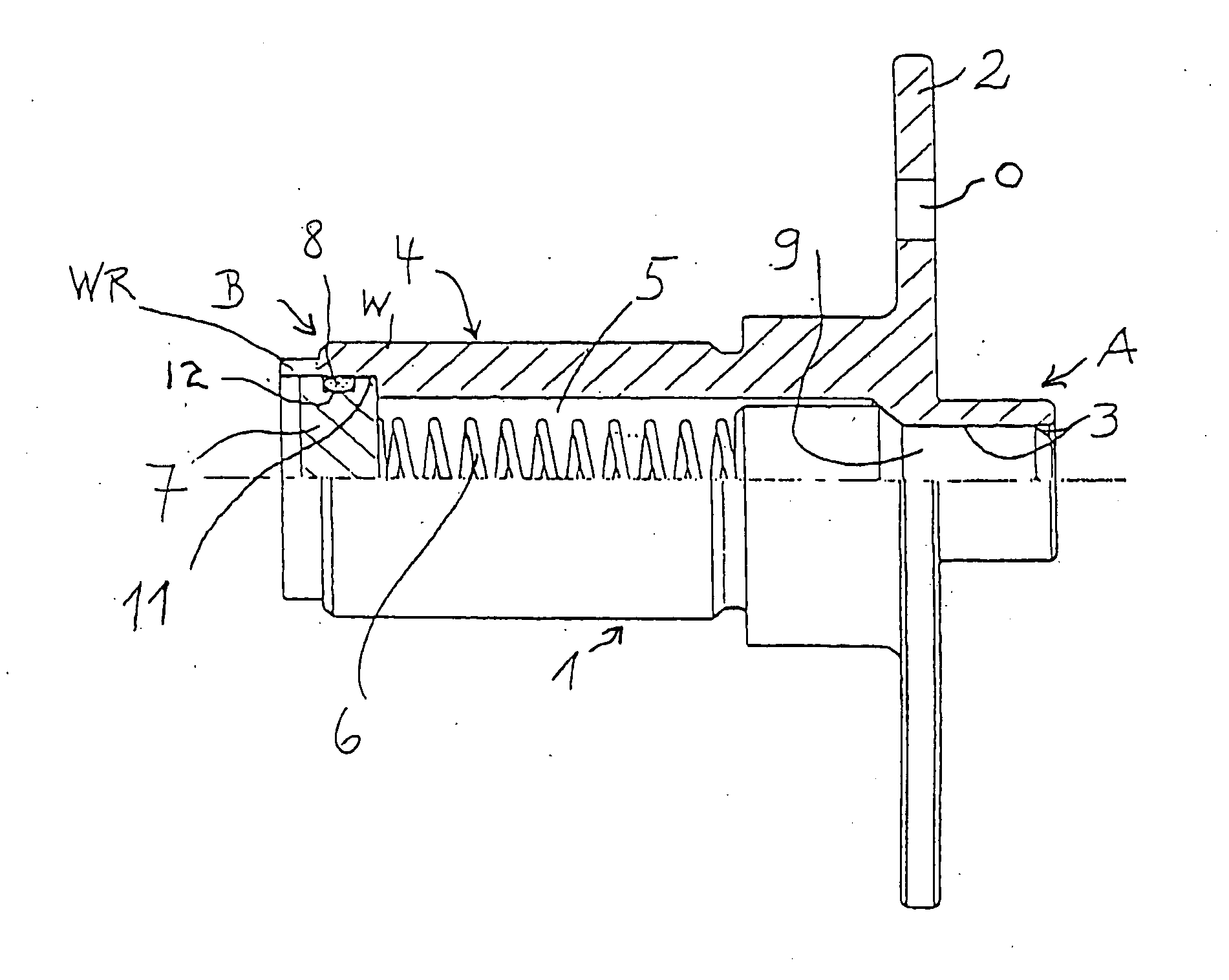
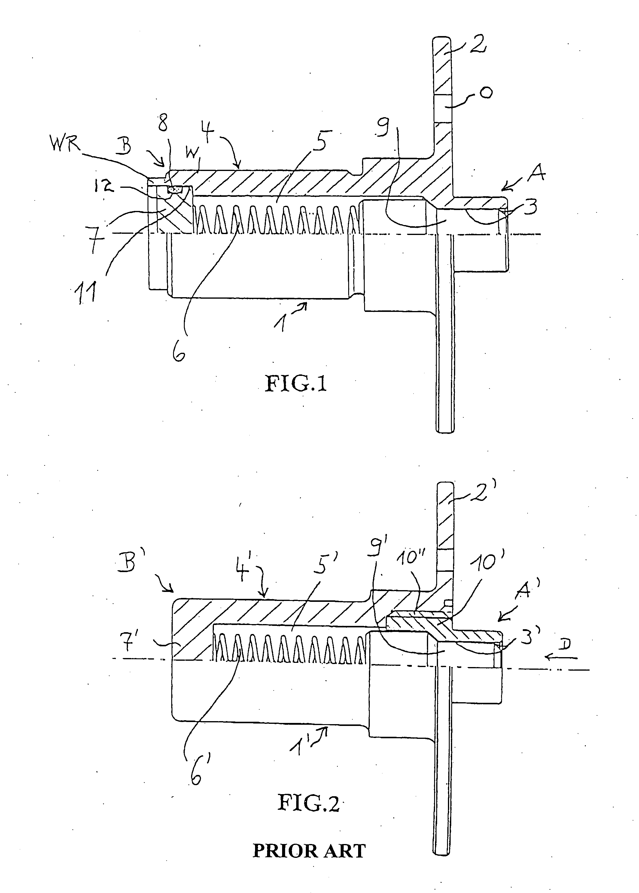
[0033] With reference to FIG. 1, the measuring-point bolt 1 has a flange 2 for attaching the bolt 1 to a wall (e.g. a wall in an aircraft) via openings O. The bolt 1 has ends A and B which can be located on opposite sides of the wall. As with the prior art device shown in FIG. 2, the bolt 1 shown in FIG. 1 is designed so tha...


PUM


Abstract

Measuring-point bolt including a body having a first end and a second end. The first end has an internal opening adapted to receive a measuring device pin. The second end is adapted connect to a hollow pin of another measuring device. A main internal opening is arranged within the body and communicates with the internal opening of the first end. A spring is arranged within the main internal opening. A element is movably arranged within the body. The element is structured and arranged to prevent entry of foreign particles into the body. A sealing member is at least one of non-removably connected to the second end and permanently fixed to the second end. The sealing member is adapted to prevent equalization of air pressure between an outside atmosphere and the main internal opening. This Abstract is not intended to define the invention disclosed in the specification, nor intended to limit the scope of the invention in any way.

Description

CROSS-REFERENCE TO RELATED APPLICATIONS [0001] The present application claims priority under 35 U.S.C. § 119 of German Patent Application No. 203 10 503.6, filed on Jul. 9, 2003, the disclosure of which is expressly incorporated by reference herein in its entirety.BACKGROUND OF THE INVENTION [0002] 1. Field of the Invention [0003] The invention relates to a measuring-point bolt for the temporary attachment of measuring devices to both ends of the bolt. [0004] 2. Discussion of Background Information [0005] The accuracy of the dimensions of certain objects (e.g. aircraft) is monitored during and after assembly, after a certain number of hours of operation, or following abnormal stress. For this purpose, measurement points are provided (e.g. on aircraft) from which the dimensional accuracy can be checked using measuring devices. [0006] Such a measuring points are formed by a bolt which is connected permanently to the wall of the aircraft and which has two free ends, i.e., one on either...

Claims


Application Information

Patent Timeline
IPC IPC(8): G01B5/00
CPCG01B5/0002
Inventor SCHWARZ, HELMUTHOMNER, BERNHARD
Owner SFS GRP INT AG
Why Eureka
Try Eureka