Personal decoration with retractable electroluminescent wire

a technology of electroluminescent wires and personal decorations, applied in the field of electroluminescent devices, can solve the problems of not being easily adjusted, predetermined length and shape, and not being readily accessible, and achieve the effect of convenient storage of an unused portion

Inactive Publication Date: 2005-02-10
ELAM T
View PDF11 Cites 6 Cited by
  • Summary
  • Abstract
  • Description
  • Claims
  • Application Information

AI Technical Summary

Benefits of technology

[0004] Some exemplary embodiments of the invention provide a device incorporating an EL wire having adjustable features, e.g., length and shape, as well as convenient storage for an unused portion of the EL wire. Furthermore, exemplary embodiments of the invention enable easy access to a power unit of a device incorporating an EL wire.

Problems solved by technology

The power supply unit is typically stowed out of sight, for example, in a concealed pocket stitched into a clothing item or inside the heel of a shoe, and is thus not readily accessible.
Prior art devices are characterized by a predetermined length and shape, which may not be readily adjusted, but which may be irreversibly cut to size.
Furthermore, the prior art devices do not facilitate easy access and rapid replacement of the power unit or units.

Method used


Image

  • Personal decoration with retractable electroluminescent wire
  • Personal decoration with retractable electroluminescent wire
  • Personal decoration with retractable electroluminescent wire

Examples


Embodiment Construction

[0017] In the following detailed description, numerous specific details are set forth in order to provide a thorough understanding of the invention. However, it will be understood by those of ordinary skill in the art that the present invention may be practiced without these specific details. In other instances, well-known methods and procedures have not been described in detail so as not to obscure the present invention.

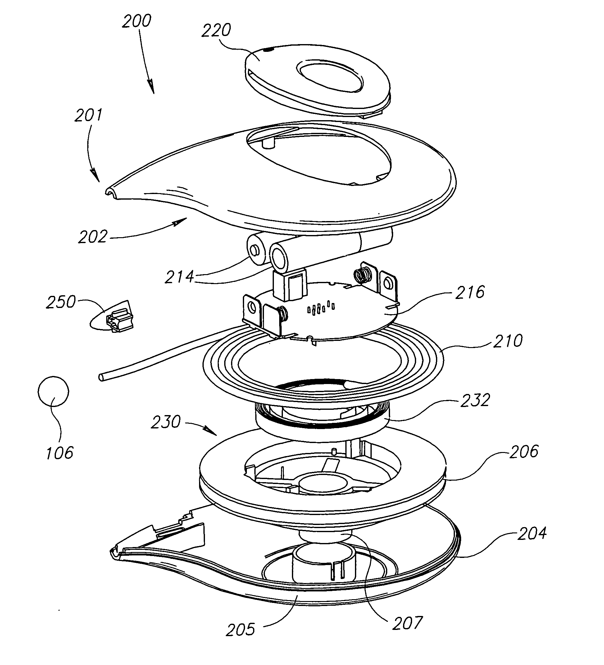
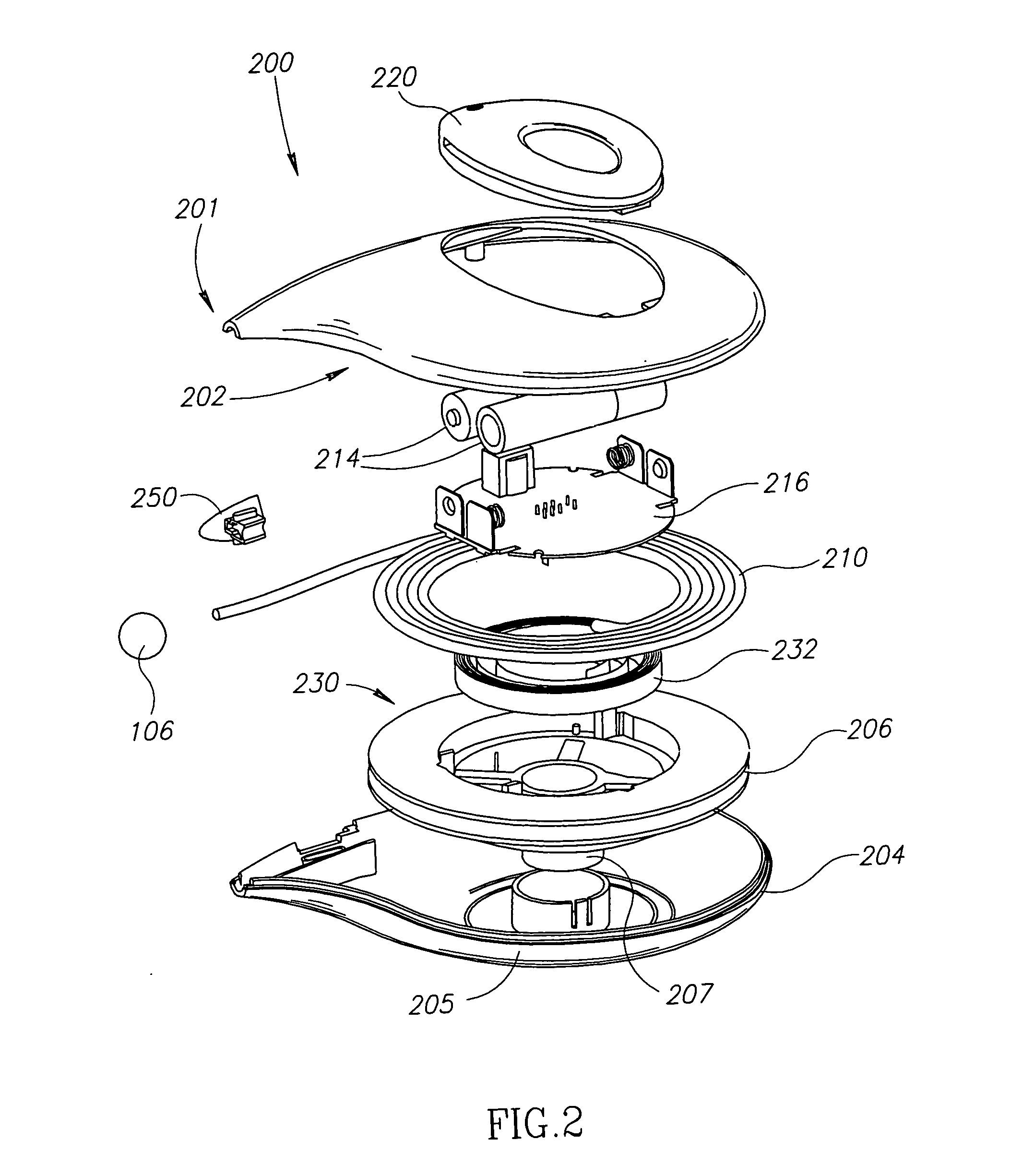
[0018] Throughout the specification and the claims, the term “spool” is used to denote a substantially cylindrical element around which an electroluminescent wire may be wound. However, it should be noted that the present invention is not limited in this respect, and other elements, providing similar functionality, may be used as part of some embodiments of the present invention, including but not limited to a bobbin, a disc and a spool.

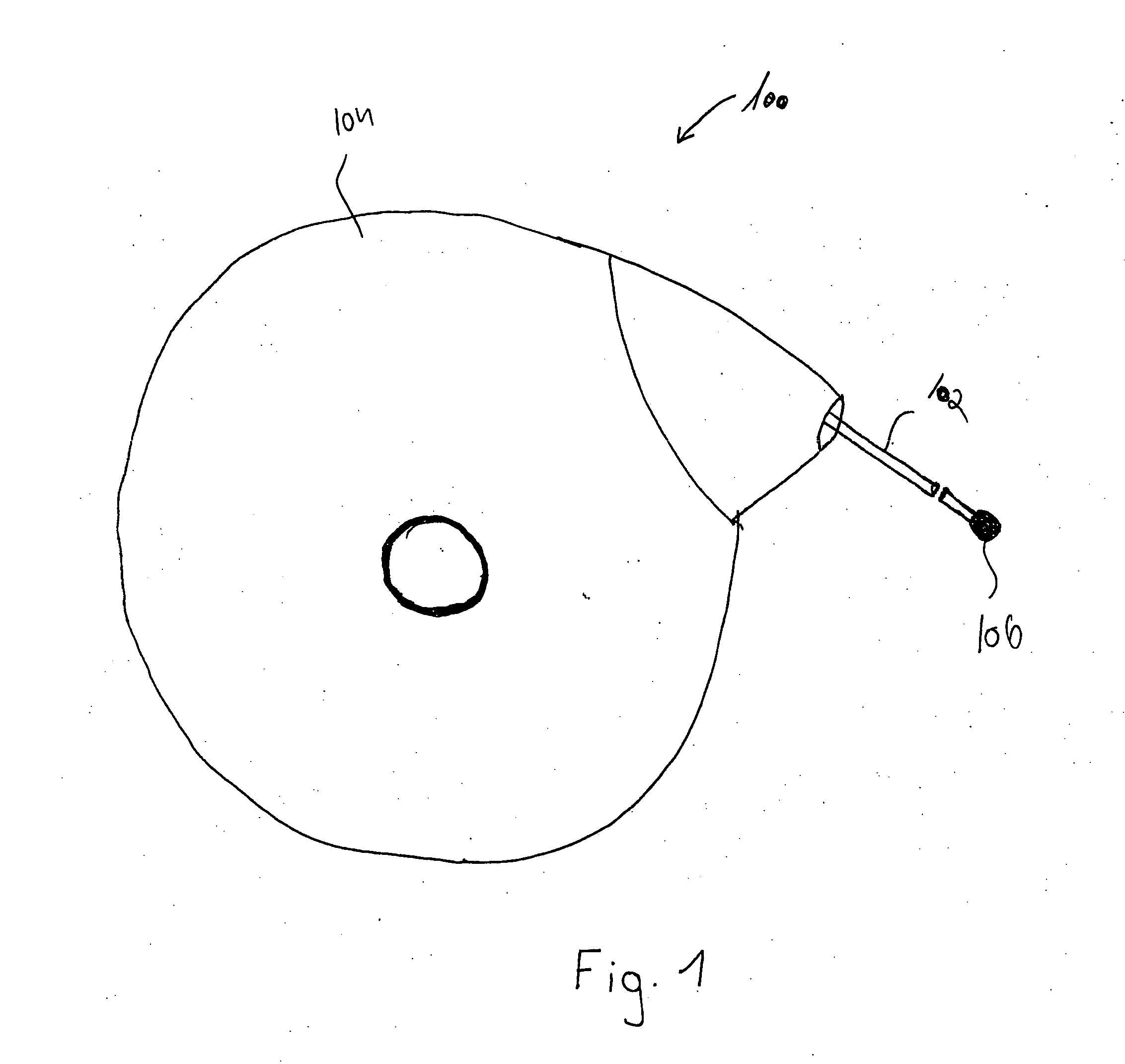
[0019] Reference is now made to FIG. 1, which schematically illustrates a top view of a device 100 including an EL wire and a cas...


PUM


Abstract

A novel device is presented having at least one electroluminescent element and a casing to house at least a portion of the electroluminescent element, allowing at least part of the electroluminescent element to be extracted from the casing and at least part of the electroluminescent element to be retracted into the casing.

Description

FIELD OF THE INVENTION [0001] The present invention relates to electroluminescent devices generally and, more specifically, to electroluminescent wires. BACKGROUND OF THE INVENTION [0002] The use of electroluminescent (EL) wires and EL strips for the purposes of personal decoration is known in the art. U.S. Pat. No. 5,485,355 (Voskoboinik), U.S. Pat. No. 5,869,930 (Baumberg) U.S. Pat. No. 6,082,867 (Chien), U.S. Pat. No. 5,479,325 (Chien), U.S. Pat. No. 5,676,451 (Tabanera), U.S. Pat. No. 5,956,071 (Feldman), US Patent Application No. 2001 / 0004808 (Hurwitz) and French Patent No. 2811206 (Simon), discuss the application of EL wires or EL strips to garments, clothing items, shoes and hats. In accordance with the prior art, the EL wires or EL strips are stitched, pasted or otherwise fixed to the object to be illuminated, for example, for decoration purposes. The power supply unit is typically stowed out of sight, for example, in a concealed pocket stitched into a clothing item or insid...

Claims


Application Information

Patent Timeline
Patent Type & Authority Applications(United States)
IPC IPC(8): A43B3/00A44C15/00
CPCA44C15/0015A43B1/0036
Inventor BOTZER, DAVIDGANOR, MICHALDVIR, JOSEPHVOSKOBOINIK, MOSHE
Owner ELAM T
Why Eureka
Try Eureka