Switch device

a switch device and switch technology, applied in the direction of emergency protective devices, connection contact material, emergency actuators, etc., can solve the problems of extremely deteriorating electrostatic voltage resistance and unsightly switch devices, and achieve excellent electrostatic voltage resistance and improved electrostatic voltage resistance

Inactive Publication Date: 2005-05-19
FUNAI ELECTRIC CO LTD
View PDF7 Cites 6 Cited by
  • Summary
  • Abstract
  • Description
  • Claims
  • Application Information

AI Technical Summary

Benefits of technology

[0013] The present invention has been made under the above situations. It is one of objects of the present invention to provide a switch device in which a push button unit has an operating portion and a shielding portion, and only the operating portion has a conductive plating layer, resulting in a pleasing appearance, and the shielding portion having no conductive plating layer shields a discharge space between a conductive plating layer of the operating portion a

Problems solved by technology

Consequently, the electrostatic voltage resistance may deteriorate extremely.
If the resin hinge 31 is repeatedly flexed and deformed, the plating layer formed

Method used


Image

  • Switch device
  • Switch device
  • Switch device

Examples


Embodiment Construction

[0023] Referring now to the accompanying drawings, a description will be given in detail of preferred embodiments of the invention.

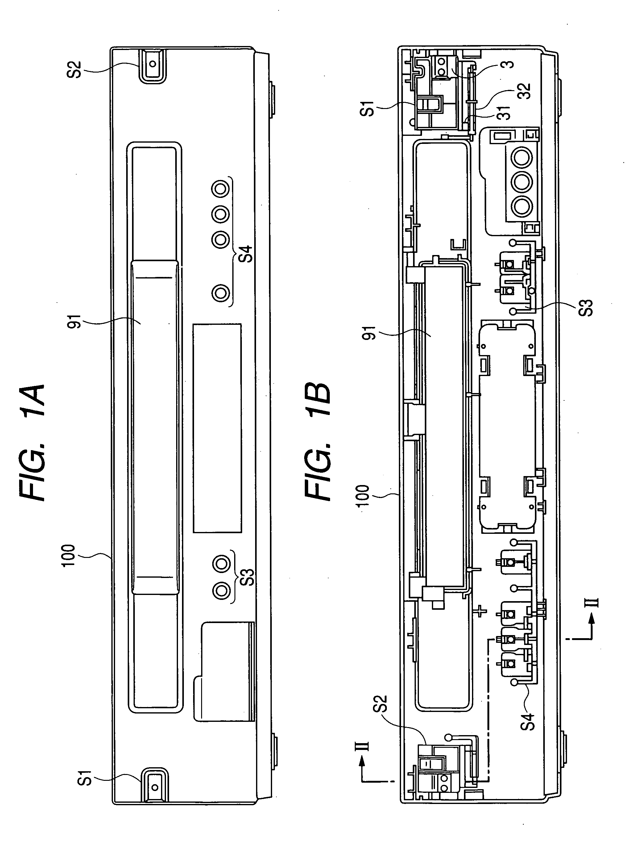
[0024] In the magnetic tape apparatus shown in FIGS. 1A and 1B, an oblong tape cassette insertion / ejection port 91 is provided at the upper center of a front panel 110 as a front cover of a housing 100, and a switch device S1 for power supply is at one side of the tape cassette insertion / ejection port 91, and a switch device S2 for stop / ejection is provided at the other side thereof. In addition, an array of buttons of a switch device S3 for channel switching and an array of buttons of a switch device S4 for operation control are arranged below the tape cassette insertion / ejection port 91.

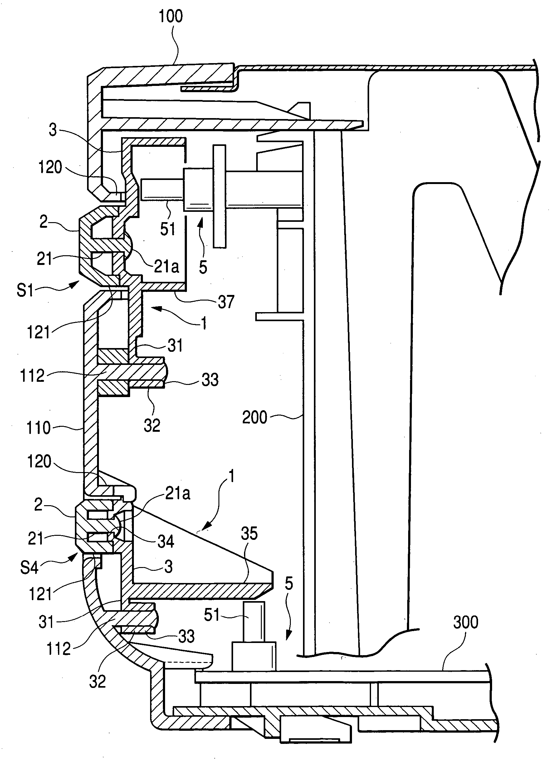
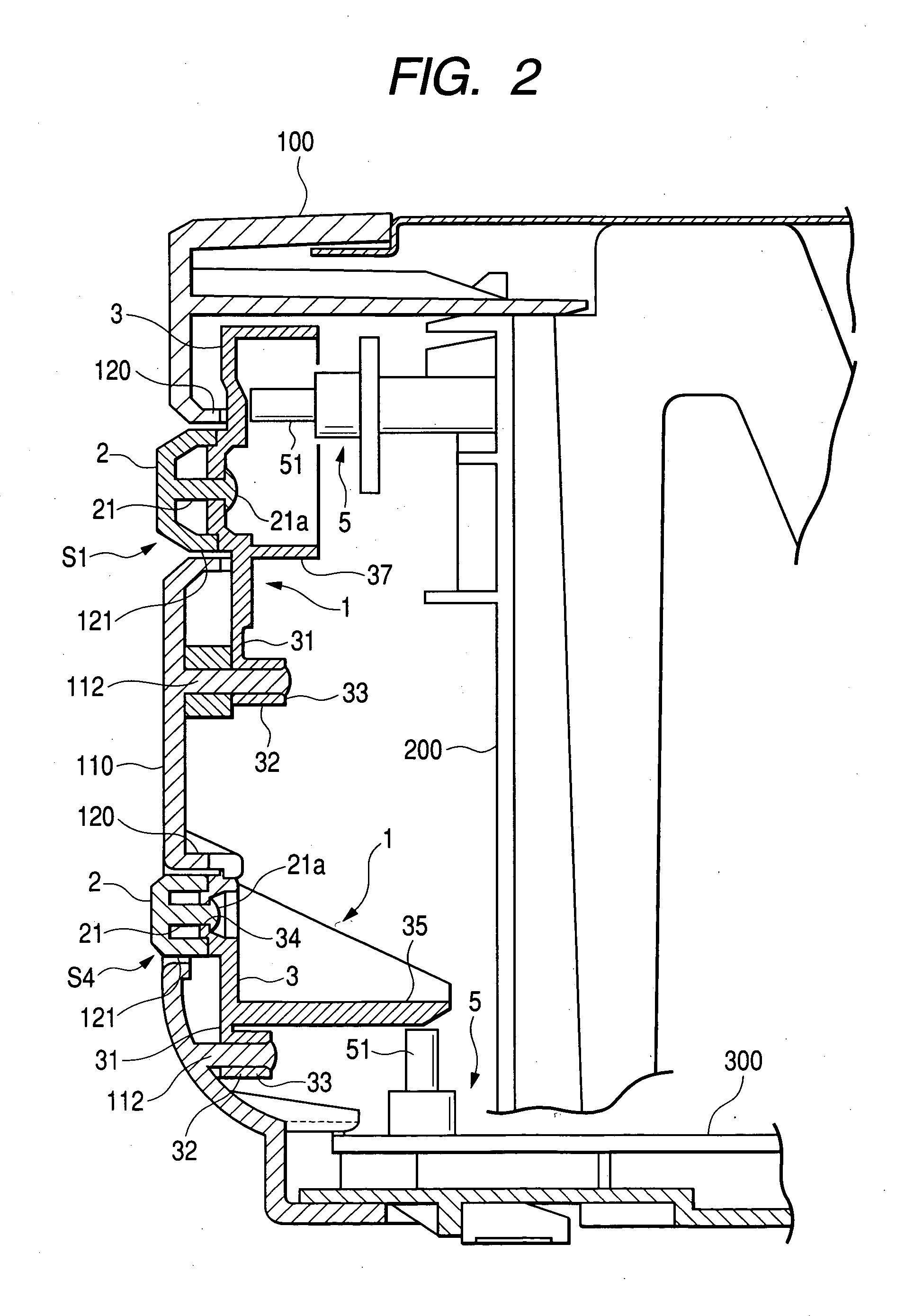
[0025] As shown in FIG. 2, in the switch device S1 for power supply, the push button unit 1 includes an operating portion 2, which is a plastic resin molding body as a push button, a shielding portion 3 projecting from a base of the operating portion 2 to the surround...


PUM


Abstract

A switch device includes: an operating portion made of a synthetic resin and having a conductive plating layer formed thereon, the operating portion configured to be inserted into a hole formed on a housing of an apparatus; and a shielding portion made of a synthetic resin and having no conducive plating layer formed thereon, the shielding portion formed separately from the operating portion and covers a gap between the operating portion and the hole from an inner side of the housing. The shielding portion is provided to push a tact of a switch provided at a rear side of the shielding portion when the shielding portion is displaced by a pushing operation of the operating portion. The operating portion is fixed to the shielding portion in a state in which the plating layer thereof being not exposed to the rear side of the shielding portion.

Description

BACKGROUND OF THE INVENTION [0001] 1. Field of the Invention [0002] The present invention relates to a switch device, and particularly, to a switch device in which a conductive plating layer is formed on an operating portion of a push button unit. [0003] 2. Description of the Related Art [0004] There is known a switch device in which a switch is combined with a push button unit having an operating portion, and the operating portion of the push button unit is pushed to change a state of the switch. In such a switch device, when a person operates the operating portion of the push button unit, static electricity discharged from the person to the switch may have a bad effect on electrical circuits connected to the switch or damage electronic components. Accordingly, measures intended for preventing the discharge of the static electricity has conventionally been taken. [0005] One of conventional measures for preventing the discharge of static electricity includes employing means in which...

Claims


Application Information

Patent Timeline
IPC IPC(8): H01H3/04H01H21/00H01H13/705
CPCH01H13/705H01H2003/466H01H2239/008H01H2221/08H01H2221/016
Inventor FUJI, TADANARI
Owner FUNAI ELECTRIC CO LTD
Why Eureka
Try Eureka