Supercharge Your Innovation With Domain-Expert AI Agents!

System decoder of digital TV

a digital tv and system technology, applied in the field of digital tv, can solve the problems of increasing the operating speed of the section filter, limiting the range, and being unable to find a proper section filter

Inactive Publication Date: 2005-08-18
LG ELECTRONICS INC
View PDF1 Cites 6 Cited by
  • Summary
  • Abstract
  • Description
  • Claims
  • Application Information

AI Technical Summary

Benefits of technology

[0031] Another object of the present invention is to provide a system decoder of a digital TV which minimizes the parts changeable according to the extension of a number of input channels in the system decoder processing multichannels.
[0035] The packet data of an input channel, the ID of the channel and the data type information thereof are stored in each packet buffer of the buffer unit, to thereby bring about the effect of remultiplexing packet data input from different channels.

Problems solved by technology

This increases an operating speed of the section filter by limiting the range of the section filter to be searched to parts.
By the way, in case the header of the section is stopped at the end of the packet, since the portion continuing in the next packet has no information, such as a table ID or the like, it is impossible to find a proper section filter.
But, the system decoders of FIG. 1 has a drawback that they are inefficient in terms of manufacturing cost because each of them has no less than three components unnecessary according to circumstances or redundant.

Method used


Image

  • System decoder of digital TV
  • System decoder of digital TV
  • System decoder of digital TV

Examples


Embodiment Construction

[0056] Hereinafter, the configuration and operation of preferred embodiments of the present invention will be described with reference to the accompanying drawings. The configuration and operation of the present invention illustrated and explained in the drawings are explained by way of at least one embodiment. Therefore, the technical idea, core configuration and operation of the present invention are not limited thereto.

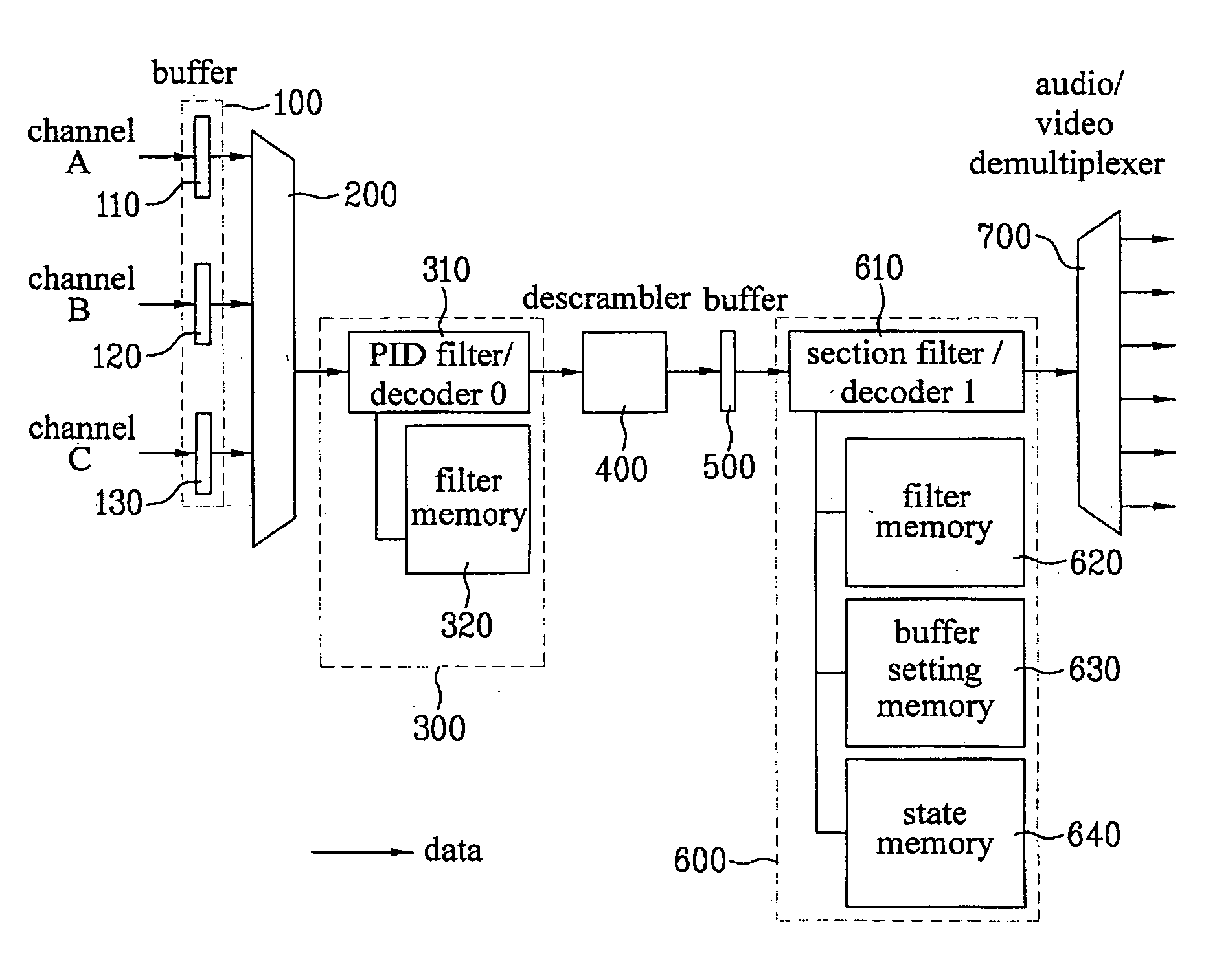
[0057]FIG. 6 is a block diagram of system decoders according to the present invention. A PID filter 310, a descrambler 400, a section filter 610, an A / V demultiplexer 700, a PID filter memory 320, a section filter memory 620, a buffer setting memory 630, and a state memory 640 are all shared by a plurality of input channels, to perform processing.

[0058] In FIG. 6, for the convenience of description, reference numeral 300 denotes a PID processing unit, and 600 denotes a section processing unit. The PID processing unit 300 includes a PID filter / decoder 310 and a PI...


PUM


Abstract

Disclosed is a system decoder of a digital TV. Particularly, the system decoder brings about the effect of remultiplexing packet data input from different channels by giving an ID to each channel, using it as an extension field of a packet ID (PID) and an extension field of a table ID of a section that are defined in the ISO / IEC 13818-1, and storing the channel ID information in the buffer transmitting packets and outputting them. Further, a memory allocated to each component can be operated without channel discrimination through the extension fields and the remultiplexing effect. Moreover, it is possible to minimize the time and cost taken to modify hardware and software so as to apply a PID filter or the like designed in a single channel to a decoder ASIC supporting a plurality of channels.

Description

[0001] This application claims the benefit of the Korean Patent Application No. 10-2004-0009643, filed on Feb. 13, 2004, which is hereby incorporated by reference as if fully set forth herein. BACKGROUND OF THE INVENTION [0002] 1. Field of the Invention [0003] The present invention relates to a digital TV, and more particularly, to a system decoder which performs PID filtering and section filtering by remultiplexing signals from a plurality of input channels. [0004] 2. Background of the Related Art [0005] With the expansion of digital TV broadcasting, the demand for multichannels is increasing. In particular, as services become diversified into ground wave, satellite, cable, etc. and the expansion of functions of, for example, a PVR (Personal Video Recorder), the necessity of simultaneously processing more than two channels is rapidly increasing. In order to simultaneously process a plurality of channels, first of all, the performance of an ASIC for processing them has to be improve...

Claims


Application Information

Patent Timeline
IPC IPC(8): H04N7/12H04L12/28H04N5/00
CPCH04N21/434A61F7/007A61F2007/0086A61H39/06A61H2201/0192A61H2201/0228A61H2201/025
Inventor RHEE, SEUNG HYEON
Owner LG ELECTRONICS INC
Features
  • R&D
  • Intellectual Property
  • Life Sciences
  • Materials
  • Tech Scout
  • Unparalleled Data Quality
  • Higher Quality Content
  • 60% Fewer Hallucinations
Learn More