Electronic still camera, instant printer and instant film

a still camera and printer technology, applied in the field of electronic still cameras, can solve the problems of unhandy carrying around, large printer body, and large amount of electric power, and achieve the effects of reducing unexpected variations in density and color, shortening the printing time, and simplifying construction

Inactive Publication Date: 2005-12-01
FUJIFILM CORP
View PDF11 Cites 24 Cited by
  • Summary
  • Abstract
  • Description
  • Claims
  • Application Information

AI Technical Summary

Benefits of technology

[0010] Using the instant film as the recording medium makes it possible to make a hard copy of an image photographed by the electronic still camera without the need for heat energy but with a low electric power. Because the printing device built in the camera scans the instant film with the printing head in a line sequential fashion while reading out the image data line by line from the memory device, the mechanical construction as well as the electrical construction of the printing device can be simple.
[0012] According to the present invention, an instant printer is comprised of a film advancing device including developing rollers for developing the processing solution in an exposed instant film; a printing head located near and before the developing rollers in the film advancing direction, the printing head having an array of light emitting elements arranged in a main scan direction perpendicular to the film advancing direction; and a head driver for driving the light emitting elements in accordance with digital image data fed to the head driver in a line sequential fashion, synchronously with the film advancing device advancing the instant film, thereby to expose the instant film line by line.
[0013] Making use of the film advancing through the developing rollers for sub scanning, the printing head does not need to move in the sub scan direction. Therefore, it takes shorter time for printing, and the construction is simplified. Although the film advancing speed is likely to fluctuate in a time period while the processing solution is developed, if timing of light emission of the printing head is controlled in accordance with the film advancing speed, it is possible to reduce unexpected variations in density and color of the printed image that may be caused by the advancing speed fluctuations. By providing an instant film with a track for detecting advancing speed of the instant film, it is easy to detect the film advancing speed, and control the light emission timing in accordance with the film advancing speed.

Problems solved by technology

Since the conventional video printers mainly use heat energy for printing, they consume certain amount of electric power.
Besides, the printer body is so large that it is unhandy to carry about.
Therefore, not being able to get a hard copy of a photographed image instantly is disadvantage to the conventional electronic still camera.

Method used


Image

  • Electronic still camera, instant printer and instant film
  • Electronic still camera, instant printer and instant film
  • Electronic still camera, instant printer and instant film

Examples


first embodiment

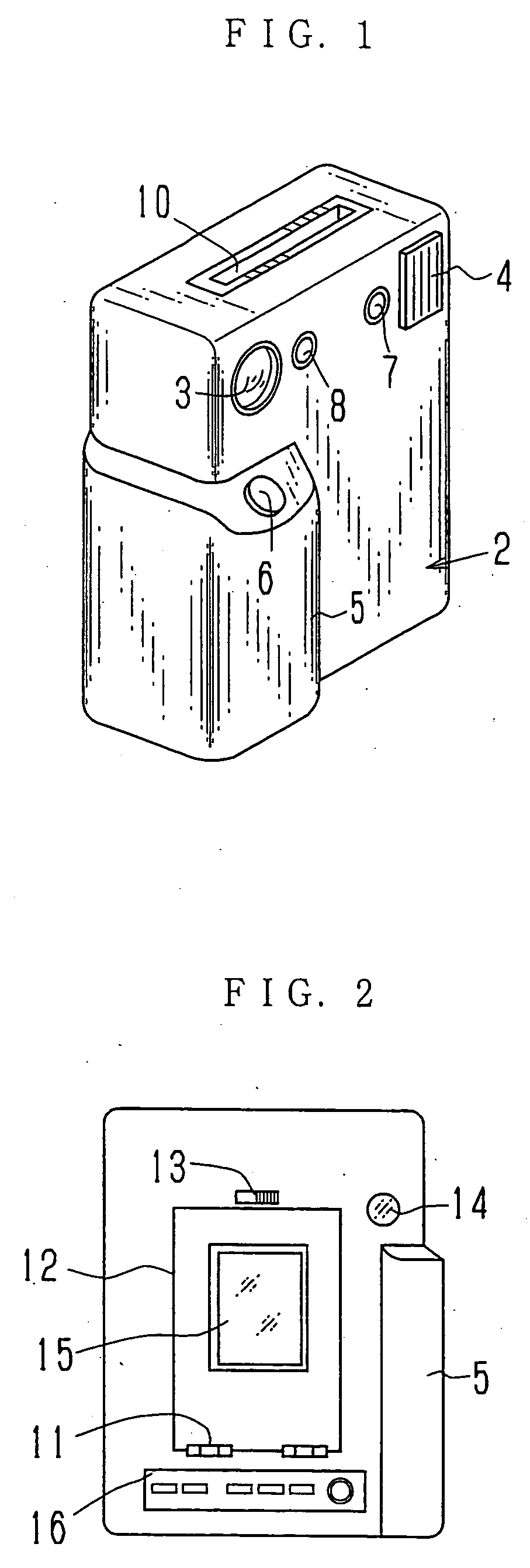
[0047] The present invention will be described in more detail with reference to the accompanying drawings. In FIGS. 1 and 2, an electronic still camera according to the invention has a camera lens 3 and a flash-emitting window 4 which are formed in the upper front surface of a camera body 2. A shutter release button 6 is located on the top of a grip 5. When the shutter release button 6 is pressed, an image is taken as a photograph through the camera lens 3. On one side of the camera lens 3 are disposed a light projector window 7 and a light receiver window 8 of an auto-focussing device for measuring a subject distance of a subject to be photographed in accordance with a technique of optical triangulation. When the shutter release button 6 is pressed, focusing of the camera lens 3 is accomplished automatically prior to the photography.

[0048] There is a film exit 10 formed as a slot in a top face of the camera body 2. When printing operation is effected, an exposed instant film is eje...

second embodiment

[0081]FIG. 8 shows a front view of an electronic still camera according to the invention. A power switch 70 is located at an upper portion of a camera body 2. When the power switch 70 is turned on, various operation keys are made effective, and the electronic still camera automatically proceeds to an imaging mode for picking up subject images. A camera lens 3 and a flash window 4 are located at upper front portions. A grip portion 5 is provided with a battery chamber lid 74 on its side area, which is opened for exchanging a power source batteries. For example, the power source batteries are four pieces of AA size batteries connected in series.

[0082] A shutter release button 75 is located at a front area of the grip portion 5. Upon the shutter release button 75 being pressed, a still image frame of the subject formed through the camera lens 3 is recorded. As the camera lens 4 is used a pan-focus lens whose depth of field ranges, for example, from 1.2 m to infinity. Therefore focusing...


PUM


Abstract

Image data obtained through an image sensor is written in a memory. When printing an image, a printing head is driven in accordance with the image data read out from the memory in a line sequential fashion, and is synchronously moved in a sub scan direction, thereby exposing the instant film line by line. The image appears on the exposed instant film as a developing solution is developed by developing rollers while the instant film is advanced out through the developing rollers. Alternatively, the printing head is driven synchronously with the instant film being advanced. Thereby an image is printed at one sub scanning without the need for moving the printing head. The printing head is provided with an array of three color light emitting elements, and three color light beams are simultaneously projected onto the instant film. The electronic still camera is automatically set in an imaging mode when a power switch is turned on, and is switched to a display mode or a print mode as soon as a display mode key or a print mode key is operated. After being switched to the display mode, the electronic still camera is quickly switched to the imaging mode if only a shutter release button is operated.

Description

FIELD OF THE ART [0001] The present invention relates to an electronic still camera that photoelectrically obtains image data through an image sensor and records the image data in a memory in a digital form, and more particularly to an electronic still camera having a printer incorporated thereinto, which makes a hard copy of an image from the image data written in the memory. The present invention also relates to an instant printer that is compact and portable, or is able to be incorporated into a camera, and an instant film for use with the instant printer. BACKGROUND ARTS [0002] Portable electronic still cameras are widely used, which convert an optical image of a subject to an electric image signal through a CCD (charge-coupled device) image sensor or the like, convert the image signal to digital image data, and write the image data in a memory. The memory is capable of storing several tens of frames of image data, and it is possible to read out the image data therefrom for disp...

Claims


Application Information

Patent Timeline
Patent Type & Authority Applications(United States)
IPC IPC(8): G03B17/48G03B17/52G03B19/02G03B27/72H04N1/00H04N1/04H04N1/10H04N1/12H04N1/193H04N1/21H04N1/387
CPCG03B17/52H04N1/00278H04N1/1017H04N2101/00H04N1/2112H04N1/2154H04N1/193
Inventor AOSAKI, KOOMURA, HIROSHIUCHIYAMA, HIROYUKINISHIURA, YOSHIKUNIHARA, TOSHITA
Owner FUJIFILM CORP
Why Eureka
Try Eureka