Impact resistant eyewear frame assembly having a split frame and fastener reinforcement

a frame and impact resistance technology, applied in the field of eyewear frame assemblies, can solve the problems of frame bulky, eyewear frames are aesthetically undesirable, eyewear frames are bulky and awkward for wearers, and the impact resistance strength of the frames is affected

Inactive Publication Date: 2005-12-22
LIBERTY SPORT
View PDF47 Cites 103 Cited by
  • Summary
  • Abstract
  • Description
  • Claims
  • Application Information

AI Technical Summary

Benefits of technology

[0006] Accordingly, it is a primary objective of the present invention to prov

Problems solved by technology

Heating of most eyewear frame materials, such as polycarbonate, to insert lenses in the eyewear frames destroys the impact resistance strength of the frames.
Still other materials require an excessively thick eyewear frame to meet the impact resistance requirements, so that the resulting eyewear frames are aesthetically undesirable, bulky and awkward for

Method used


Image

  • Impact resistant eyewear frame assembly having a split frame and fastener reinforcement
  • Impact resistant eyewear frame assembly having a split frame and fastener reinforcement
  • Impact resistant eyewear frame assembly having a split frame and fastener reinforcement

Examples


first embodiment

Assembly and Disassembly of First Embodiment of FIGS. 1-6

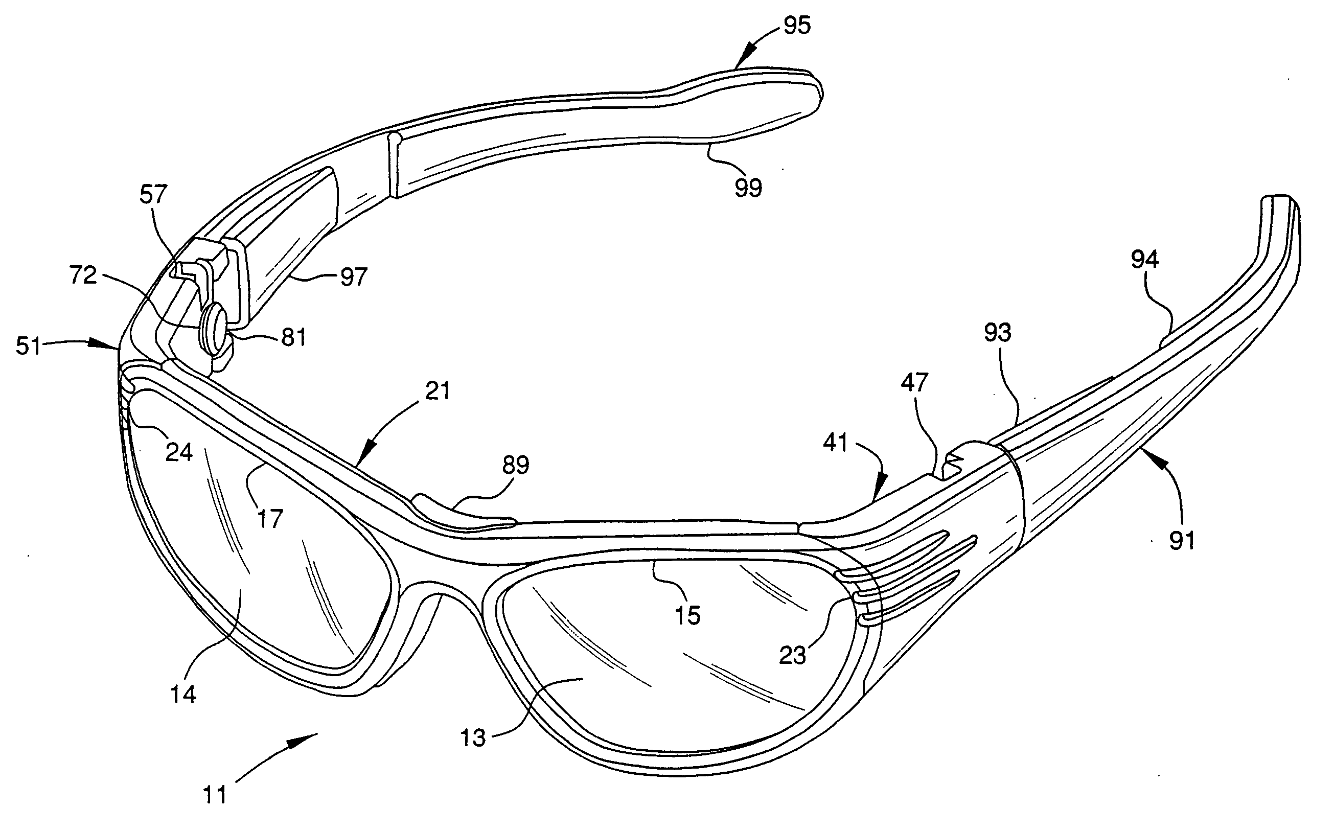
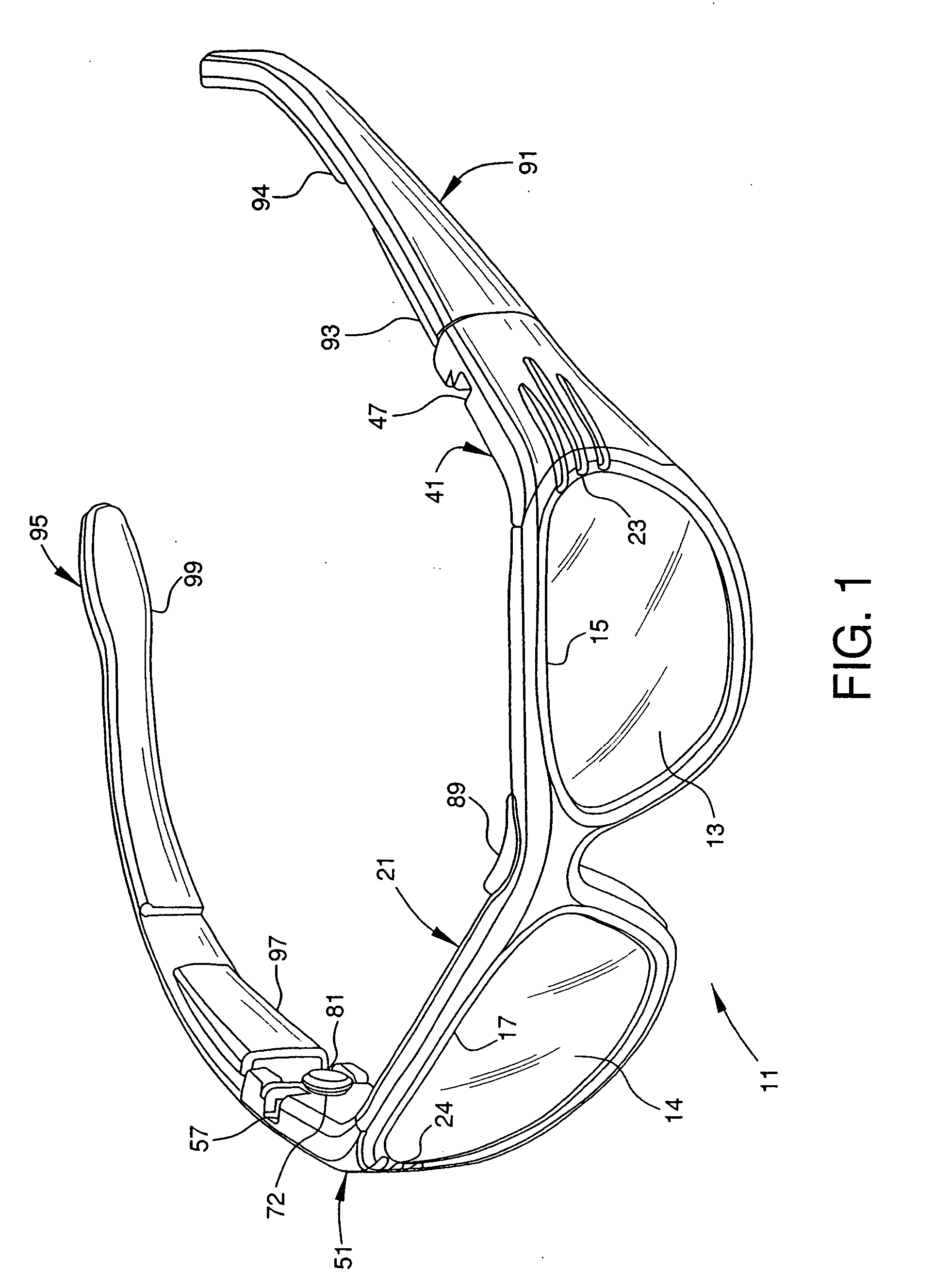
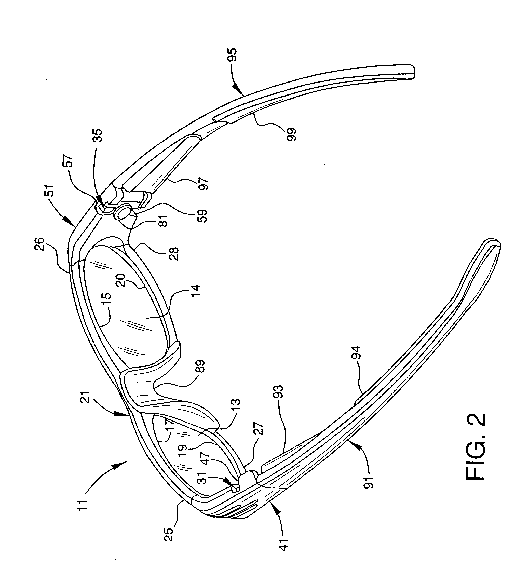
[0032] A fully assembled eyewear frame assembly 11 is shown in FIGS. 1-3. The eyewear frame assembly 11 is assembled by connecting the various components shown in FIGS. 4 and 5.

[0033] The first upper and lower portions of the frame 25 and 27 are pulled apart at the first split 23 so that a first lens 13 may be inserted in the first groove 16. Once the lens is inserted, the resiliency of the frame pulls the first upper and lower portions 25 and 27 back together. First and second projections 31 and 33 are then inserted into the opening 42 at the first end 44 of the first sleeve 41, as shown in FIG. 5. The first and second tapered portions 32 and 34 contact the first and second inwardly extending tapered tabs 43 and 45, which force the first and second projections inwardly toward one another as they pass the tapered tabs. Once the first and second projections 31 and 33 pass the tapered tabs, the resiliency of the projections cau...

second embodiment

of FIGS. 7-9

[0038] A second embodiment of the present invention is shown in FIGS. 7-9 as eyewear frame assembly 111. This second embodiment is substantially the same as the first embodiment of FIGS. 1-6 and like reference numerals are used in FIGS. 7-9 with the addition of 100 thereto to refer to similar elements as in the first embodiment. The second embodiment is modified by the addition of a threaded fastener 200 and a threaded bushing 202, as well as related structure, received inside the sleeve 141 to form a reinforcement assembly for the upper and lower portions 125 and 127 and the first and second projections 131 and 133 of the split frame 121. This reinforcement assembly advantageously helps to keep the split frame portions 125 and 127 and projections 131 and 133 located thereon together during various vigorous activities, in addition to the sleeve 141, so that the lenses, such as lens 113, do not easily fall out of the frame.

[0039] More specifically, as seen in FIGS. 7-9, ...


PUM


Abstract

The present invention provides an eyewear frame assembly. A frame has an aperture for receiving a lens. The frame has a split to expand upper and lower portions of the frame to insert or remove the lens from the aperture. First and second projections extend outwardly from the upper and lower frame portions, respectively. The first and second projections have first and second tapered portions, respectively. A sleeve receives said first and second projections. The sleeve has first and second inwardly extending and tapered tabs adapted to receive the first and second tapered portions to secure the first and second projections within the sleeve. The upper and lower portions of the frame are prevented from expanding when the first and second projections are received within the sleeve. First and second openings in the sleeve provide access to depress the first and second projections to remove the first and second projections from the first and second sleeves. A threaded fastener and a threaded sleeve forms a reinforcement assembly for the two portions of the split frame. The sleeve engages the fastener to resist its disengagement with the bushing.

Description

RELATED APPLICATIONS [0001] This application is a continuation-in-part of U.S. patent application Ser. No. 10 / 391,796 filed Mar. 20, 2003 for Impact Resistant Eyewear Frame Assembly Having a Split Frame, the disclosure of which is hereby incorporated herein by reference.FIELD OF THE INVENTION [0002] The present invention relates to an eyewear frame assembly that is impact resistant. More particularly, the present invention relates to an impact resistant eyewear frame assembly having a split frame for easily inserting and removing a lens. Still more particularly, the present invention relates to an impact resistant split frame having projections adapted to be received by a sleeve to secure a lens within the frame, as well as a threaded fastener and a threaded bushing received inside the sleeve to form a reinforcement assembly for two portions on the split frame. BACKGROUND OF THE INVENTION [0003] Eyewear frame assemblies often need to be impact resistant, such as when worn for sporti...

Claims


Application Information

Patent Timeline
IPC IPC(8): G02C1/08
CPCG02C1/08G02C5/146G02C2200/08G02C2200/06G02C2200/04
Inventor DICHIARA, CARMINE S.LEONARDI, PETER S.
Owner LIBERTY SPORT
Why Eureka
Try Eureka