Disc apparatus

a technology of discs and components, applied in the direction of disposing/mounting heads, data recording, instruments, etc., can solve the problems of increasing the number of components and complicated apparatus structure, and achieve the effect of reducing the number of components and the size of the apparatus

Active Publication Date: 2005-12-22
FUNAI ELECTRIC CO LTD
View PDF12 Cites 4 Cited by
  • Summary
  • Abstract
  • Description
  • Claims
  • Application Information

AI Technical Summary

Benefits of technology

[0012] An object of the present invention is to provide a disc apparatus that enables reduction in the number of component

Problems solved by technology

The disc apparatuses disclosed in Japanese Patent Laying-Open Nos. 2003-085855 and 2002-329361 and in Japanese Utility Model Registra

Method used


Image

  • Disc apparatus
  • Disc apparatus
  • Disc apparatus

Examples


Embodiment Construction

[0027] In the following, an embodiment of the present invention will be described with reference to the figures.

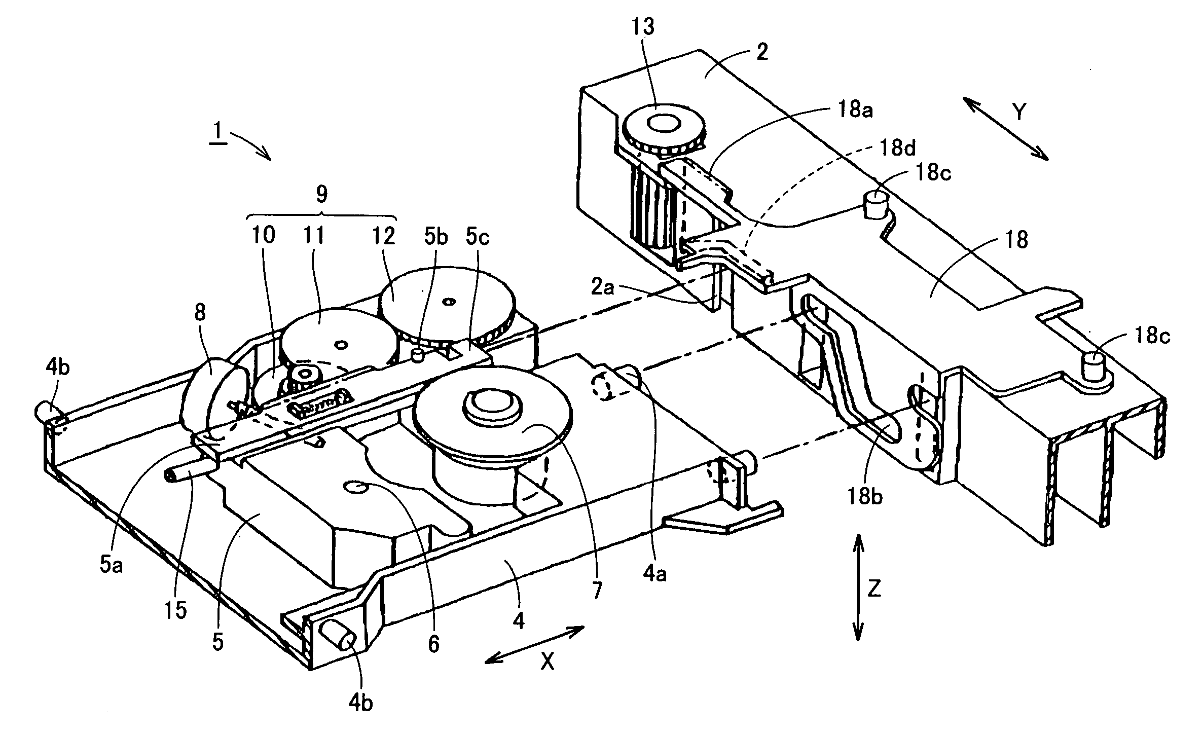
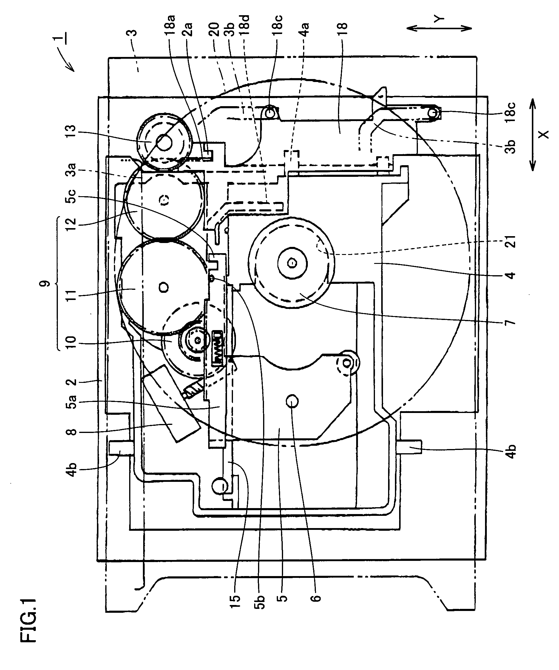
[0028] Referring to FIGS. 1 and 2, a disc apparatus 1 in accordance with the present embodiment has a chassis 2. A disc tray 3 and a drive unit 4 are mounted on chassis 2. Disc tray 3 is movably supported by chassis 2, and movable in the direction of an arrow X in the figures. On a pair of side surfaces of drive unit 4, pins 4b are provided, respectively, which pins 4b are pivotally supported by a bearing portion formed in chassis 2. Therefore, drive unit 4 is supported by chassis 2 to be movable upward / downward about pins 4b as axes, and it can be moved upward / downward in the direction of an arrow Z in the figure (in the direction vertical to the sheet surface in FIG. 1).

[0029] A turntable 7 as a chucking portion is fixed on drive unit 4. As drive unit 4 moves upward / downward, turntable 7 is engaged with / disengaged from a hole portion 21 of a disc 20 placed on disc tray...


PUM


Abstract

A disc apparatus includes a chassis, a drive unit driven by a motor to be moved upward/downward in a prescribed direction, and a pick-up unit having a pick-up and driven by the motor to be moved in a direction orthogonal to the direction of upward/downward movement of the drive unit. The pick-up unit has an interlocking piece, and the chassis has an interlocking portion that can be interlocked with interlocking piece. In the disc apparatus, the interlocking piece provided in the pick-up unit is interlocked with the interlocking portion provided in the chassis when the drive unit is in a lowered state, whereby the pick-up unit is locked into the chassis. Therefore, reduction in the number of components and in the size of the apparatus becomes possible, and the lock mechanism of the pick-up unit can be formed in a simple structure.

Description

BACKGROUND OF THE INVENTION [0001] 1. Field of the Invention [0002] The present invention relates to a disc apparatus for reproducing, recording or erasing a magnetic disc or an optical disc represented, for example, by a DVD (Digital Versatile Disc) (hereinafter simply referred to as a disc) and, more specifically, to a lock mechanism of a pick-up unit mounted on such a disc apparatus. [0003] 2. Description of the Background Art [0004] Generally, a disc apparatus includes, in its main body, a disc tray conveying a disc, and a drive unit movable in a direction approximately vertical to the direction of conveying the disc tray. The drive unit includes a pick-up unit having a pick-up for recording or reproduction of the disc, and a motor for moving the pick-up unit along radial direction of the disc. [0005] A transmitting portion including a plurality of gears is provided on the motor, for reducing and transmitting the driving force of the motor. When the transmitting portion meshes w...

Claims


Application Information

Patent Timeline
IPC IPC(8): G11B17/04
CPCG11B17/056
Inventor IWAASA, HIROAKI
Owner FUNAI ELECTRIC CO LTD
Why Eureka
Try Eureka