

Hard disk drive with damping plate
- Summary
- Abstract
- Description
- Claims
- Application Information
AI Technical Summary
Benefits of technology
Problems solved by technology
Method used
Image

Examples
Embodiment Construction
[0030] Reference will now be made in detail to the embodiments of the present invention, examples of which are illustrated in the accompanying drawings, wherein like reference numerals refer to the like elements throughout. The embodiments are described below to explain the present invention by referring to the figures.
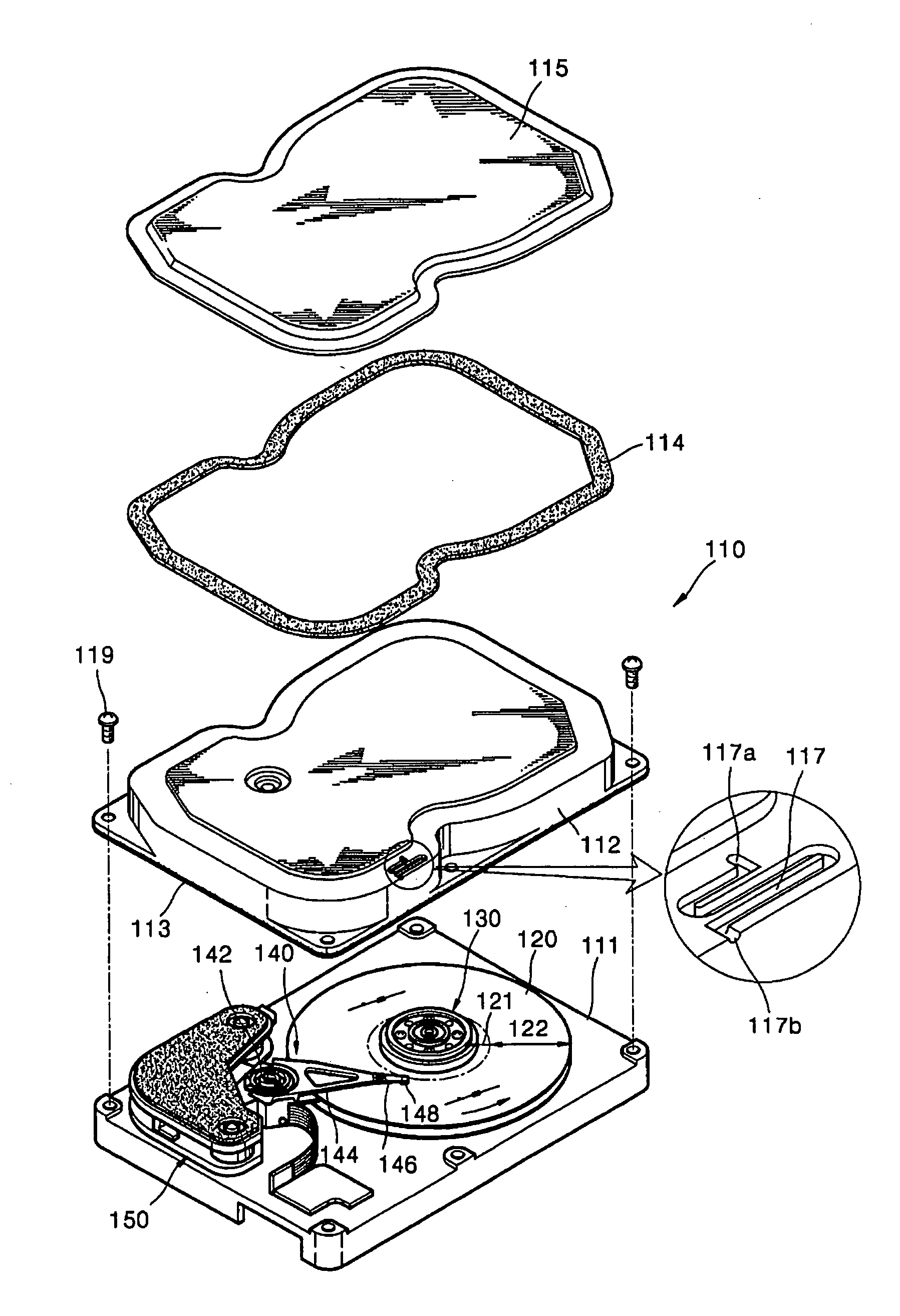
[0031] Referring to FIGS. 3 and 4, a hard disk drive having a housing, according to an embodiment of the present invention, may include a disk 120 for storing data, a spindle motor 130 for rotating the disk 120, and an actuator 140 for moving a read / write head to a predetermined position over the disk 120. The disk 120, the spindle motor 130, and the actuator 140 can be encompassed and protected by a housing 110.
[0032] The disk 120 may be a recording medium recording data, with one or a more disks being installed on the spindle motor 130 and rotated by the spindle motor 130. A parking zone 121, where the head is parked when the hard disk drive stops operation, and a...
PUM
 Abstract
Description
Claims
Application Information