Polyaxial screw

a polyaxial screw and screw head technology, applied in the field of orthopaedic surgery, can solve the problem that the screw head is usually misaligned relative to the other side, and achieve the effect of preventing cross threading of components

Active Publication Date: 2006-02-16
INNOVATIVE SPINAL DESIGN +1
View PDF89 Cites 461 Cited by
  • Summary
  • Abstract
  • Description
  • Claims
  • Application Information

AI Technical Summary

Benefits of technology

[0010] It is yet another objective of this invention to p

Problems solved by technology

Because of the non-uniform anatomy of the vertebrae, th

Method used


Image

  • Polyaxial screw
  • Polyaxial screw
  • Polyaxial screw

Examples


Embodiment Construction

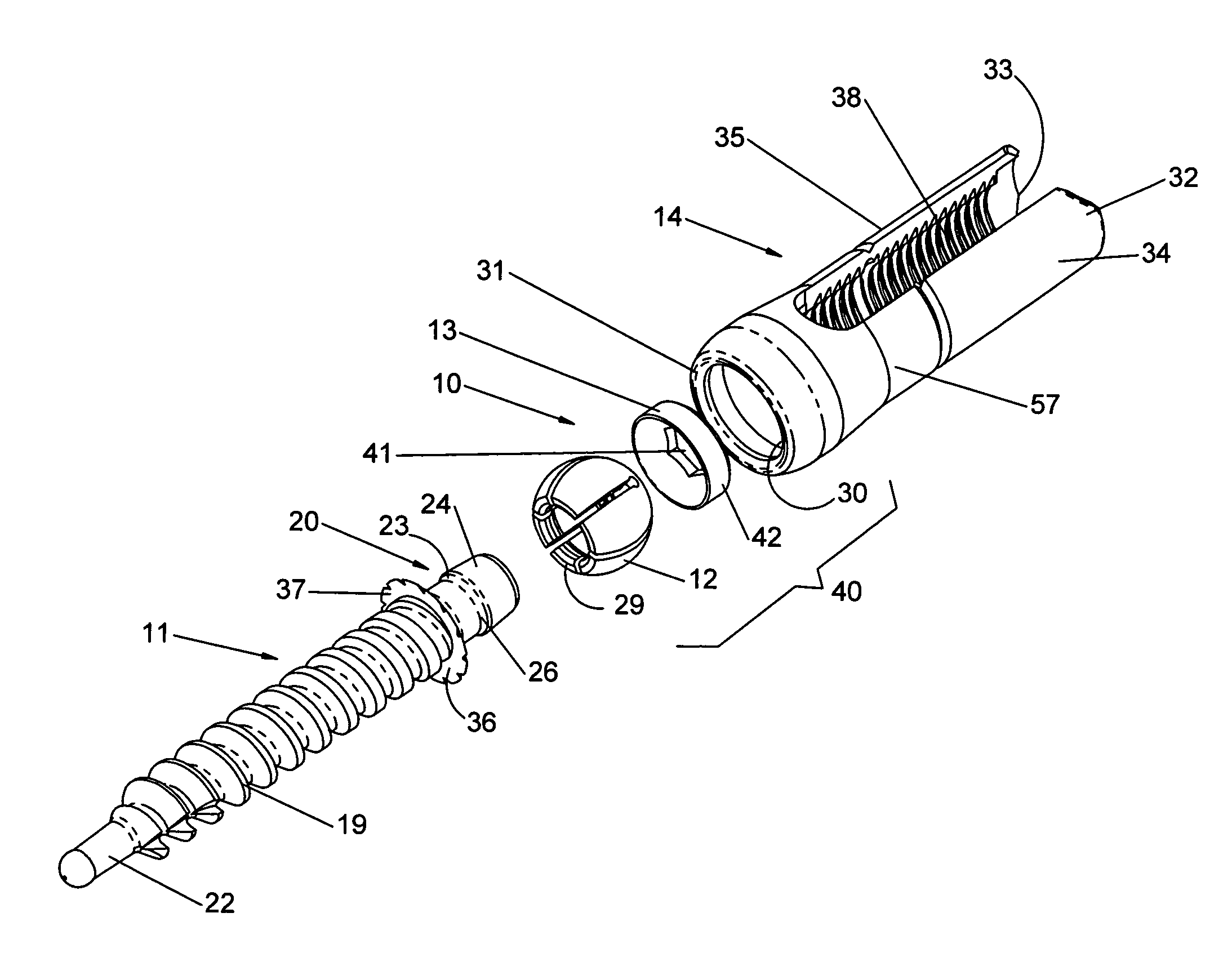
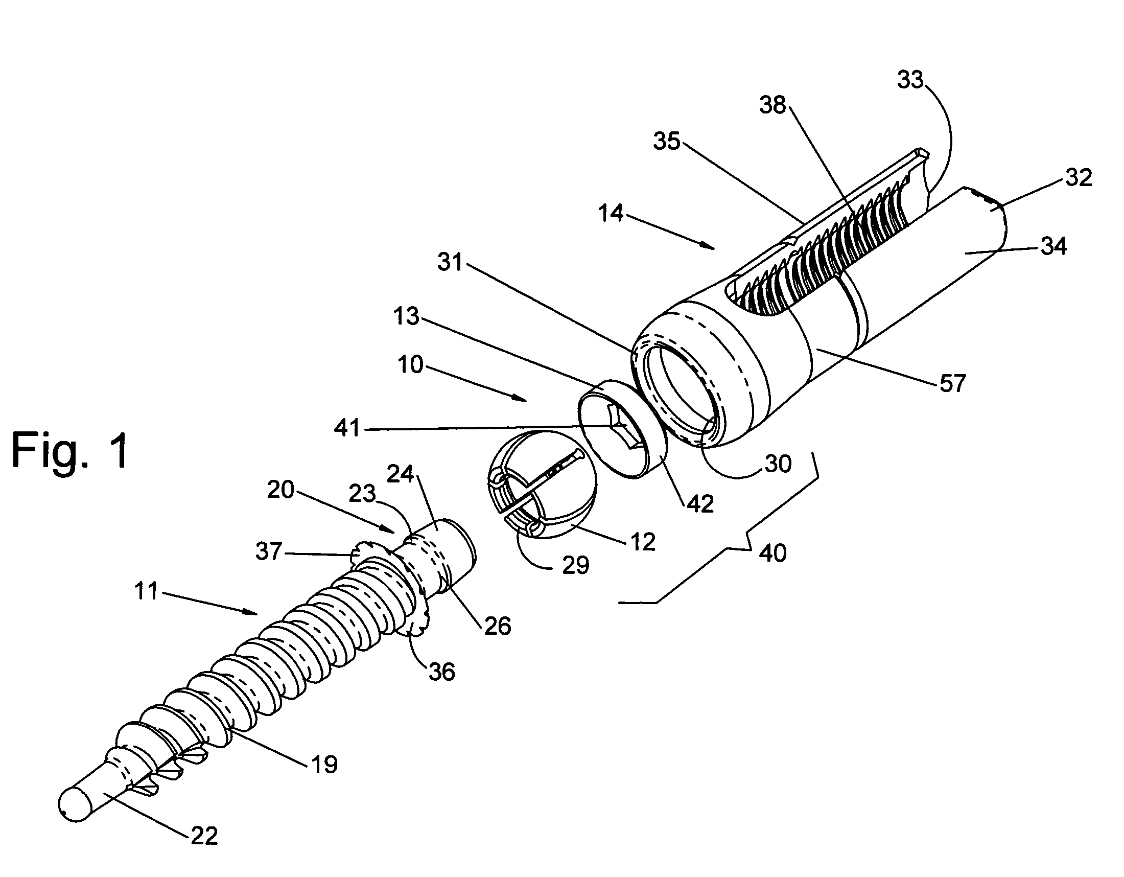
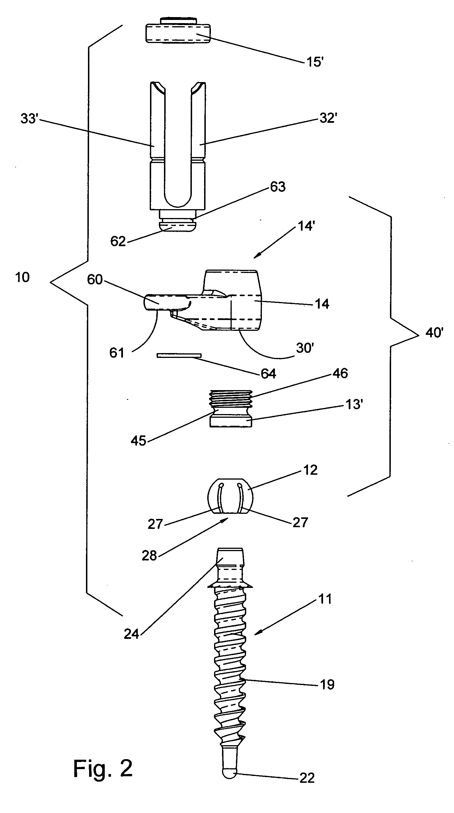
[0020] The polyaxial screw assembly 10, shown in FIGS. 1-2, is composed of a bone or pedicle screw 11, a collet or swivel 12, a ring or collar 13, 13′, a connector 14, a guide or locking ring 15, and a set screw or nut 16. In FIG. 3, a surgical appliance, such as a spinal rod 17 is illustrated positioned between the connector 14 and the nut 16. The polyaxial screw assembly may be used in conjunction with spinal rods, hooks or other surgical appliances that require securement to the skeletal structure.

[0021] The bone screw 11, shown in FIGS. 1-3, has a shaft 18 having a helical thread 19 for drilling into the skeleton of a patient. A reverse tapered head 20 has a bore 21 for engagement with a tool (not shown) for turning the screw into the bone. The leading end 22 of the screw may be self tapping or used with pre-drilled holes. The head 20 has its greatest diameter at the shoulder 23. The head has a taper 24 from the shoulder toward the leading end and another taper 25 from the shou...


PUM


Abstract

A polyaxial screw is used to secure orthopedic appliances to bone, particularly the spine. The polyaxial screw has a shaft including a helical screw thread for securing the screw to bone. One end of the shaft has a reverse tapered head tapering toward and away from the shaft from an enlarged median. A spherical shaped swivel, having an opening smaller than the median, is snapped over the head to rotatably engage the shaft. A connector with a dome shaped cavity on one end and bifurcated tabs on the other is connected with the swivel and tightened in place with a set screw and guide ring. An appliance is held between the bifurcated tabs. The tabs are frangible to reduce the profile above the appliance.

Description

BACKGROUND OF THE INVENTION [0001] 1. Field of the Invention [0002] This invention relates to the field of orthopedic surgery and, particularly to modular screws having a polyaxial head. [0003] 2. Description of the Prior Art [0004] It is conventional to install surgical appliances, such as rods or plates, to correct skeletal deformities and injuries in which the appliance spans several vertebrae. The surgical appliance is secured to the vertebrae and maintains a stable spatial relationship between them. Pedicle screws are inserted into the vertebrae to anchor the appliance in place. Because of the non-uniform anatomy of the vertebrae, the screws are usually misaligned relative to each other. To compensate for these variances, the rods may be bent to match the location of the screws or the screws may have connectors capable of angular displacement to engage the rods or both. [0005] For example, U.S. Pat. No. 6,669,697 to Pisharodi teaches the use of eccentric shims between the bone ...

Claims


Application Information

Patent Timeline
IPC IPC(8): A61B17/86A61B17/70
CPCA61B17/7035A61B2019/307A61B17/7041A61B17/7037A61B2090/037
Inventor BAYNHAM, BRET O.BAYNHAM, G. CLAYBAYNHAM, MATTHEW G.CAMPBELL, DAVID R.
Owner INNOVATIVE SPINAL DESIGN
Why Eureka
Try Eureka