Miniaturized lens assembly

a lens assembly and miniature technology, applied in the field of miniature lens assembly, can solve the problems of troublesome process for making the conventional lens assembly and relatively complicated installation of the conventional lens assembly, and achieve the effects of convenient assembly, convenient testing, and simple structur

Inactive Publication Date: 2006-03-30
ASIA OPTICAL CO INC
View PDF5 Cites 0 Cited by
  • Summary
  • Abstract
  • Description
  • Claims
  • Application Information

AI Technical Summary

Benefits of technology

[0015] The object of the present invention is to provide a miniaturized lens assembly which is simple in structure, which is miniature in size, and which is relatively easy to assemble and convenient to test.

Problems solved by technology

Therefore, the process for making the conventional lens assembly is troublesome.
Therefore, the installation of the conventional lens assembly is relatively complicated.

Method used


Image

  • Miniaturized lens assembly
  • Miniaturized lens assembly
  • Miniaturized lens assembly

Examples


Embodiment Construction

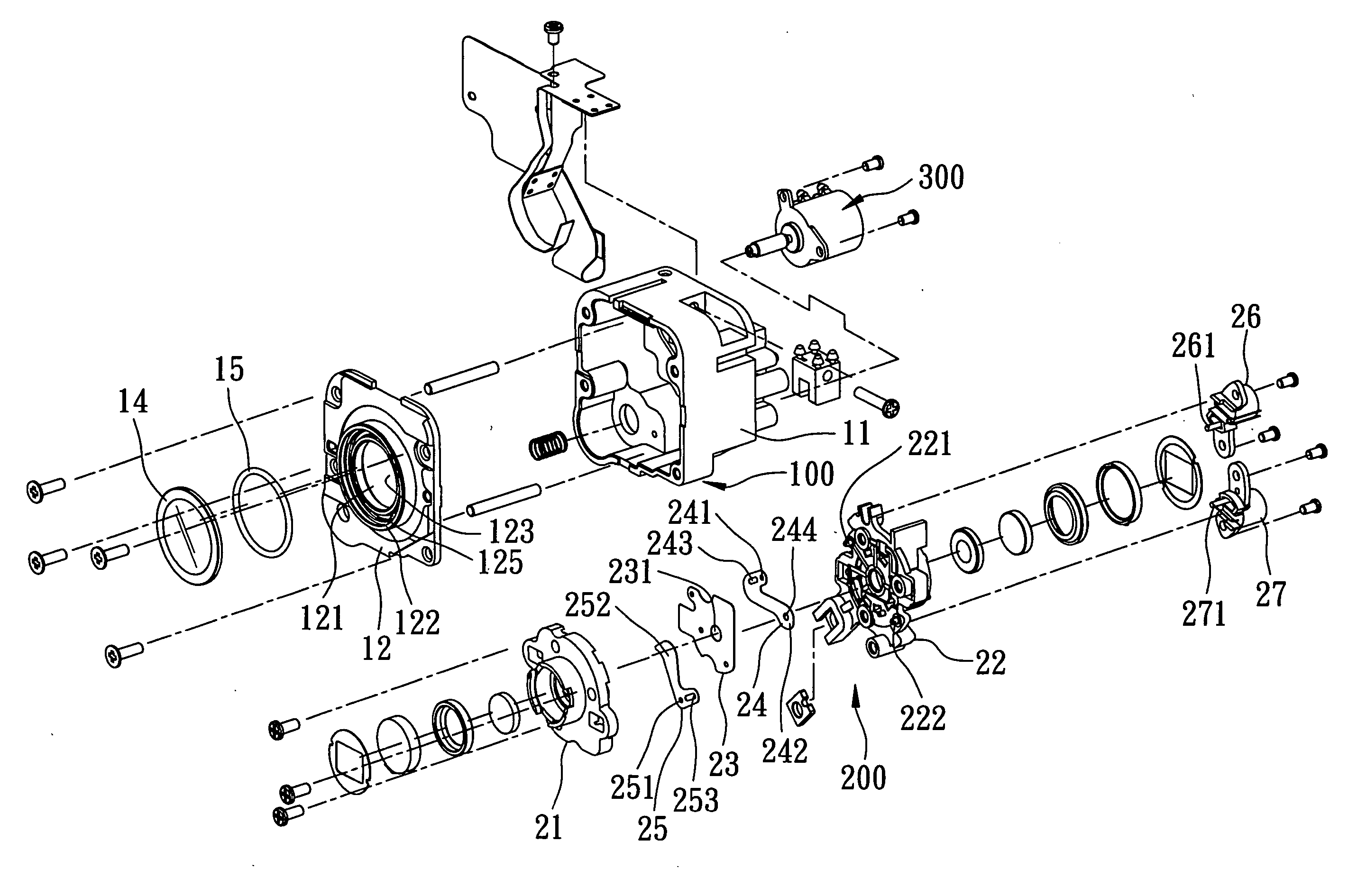
[0028] Referring to FIGS. 5 and 6, the preferred embodiment of the miniaturized lens assembly according to this invention includes a shell unit 100, a lens unit 200 mounted in the shell unit 100, and a motor 300 mounted on the shell unit 100 for actuating the lens unit 200. As the configuration for connecting the motor 300 to the lens unit 200 is well known to the skilled artisan, it will not be described herein in detail.

[0029] The shell unit 100 includes a receiving box 11 having a lens hole 111, and a cap 12 having a lens hole 121 aligned with the lens hole 111 of the receiving box 11 along a longitudinal axis (L). The receiving box 11 cooperates with the cap 12 to define a receiving space 13 for receiving the lens unit 200. The lens hole 121 of the cap 12 is formed as a stepped hole configuration, and includes a large diameter ring portion 122, a small diameter ring portion 123, a shoulder face 124 between the large and small diameter ring portions 122, 123, and an annular groo...


PUM


Abstract

A miniaturized lens assembly includes a front lens portion, a rear lens portion, a large diaphragm plate mounted between the front and rear lens portions, a small diaphragm plate rotatable relative to the large diaphragm plate, a shutter plate rotatable relative to the large diaphragm plate, first and second actuating elements mounted on the rear lens portion, and two pivot axles mounted between the front and rear lens portions. The miniaturized lens assembly is miniature in size, is simple in structure, and is easy to assemble.

Description

CROSS-REFERENCE TO RELATED APPLICATION [0001] This application claims priority of Taiwanese Application No. 093129021, filed on Sep. 24, 2004. BACKGROUND OF THE INVENTION [0002] 1. Field of the Invention [0003] The invention relates to a lens assembly, more particularly to a miniaturized lens assembly. [0004] 2. Description of the Related Art [0005] Referring to FIGS. 1, 2 and 3, a conventional lens assembly includes a shell unit 1, a lens unit 2 received in the shell unit 1, and a motor 3 for actuating the lens unit 2. [0006] The shell unit 1 has a peripheral wall 101 and a guiding groove 102 in the peripheral wall 101. [0007] The lens unit 2 has a front lens portion 4, a rear lens portion 5 opposite to the front lens portion 4 along a longitudinal axis (X), a large diaphragm plate 6 mounted between the front lens portion 4 and the rear lens portion 5, a small diaphragm plate 7 mounted pivotally between the front lens portion 4 and the rear lens portion 5 and rotatable relative to ...

Claims


Application Information

Patent Timeline
Patent Type & Authority Applications(United States)
IPC IPC(8): G03B9/08
CPCG03B9/08
Inventor HUANG, YAO-CHING
Owner ASIA OPTICAL CO INC
Why Eureka
Try Eureka