Vehicular drive system

Inactive Publication Date: 2006-05-18
TOYOTA JIDOSHA KK
View PDF11 Cites 34 Cited by
  • Summary
  • Abstract
  • Description
  • Claims
  • Application Information

AI Technical Summary

Benefits of technology

[0023] Using a gear set as the power transmitting means between the first axis and the second axis obviates the need for a third axis to reverse the rotation of the second axis, which is necessary when a belt is used as the

Problems solved by technology

Thus, while it is possible to mount this vehicular drive system longitudinally in a FR (front-engine-rear-drive) vehicle, it is difficult to mount transversely in a FF (front-engine-front-drive) vehicle or a RR (rear-engine-rear-drive) vehi

Method used


Image

  • Vehicular drive system
  • Vehicular drive system
  • Vehicular drive system

Examples


Embodiment Construction

[0038] Next, exemplary embodiments of the invention will be described in detail with reference to the accompanying drawings.

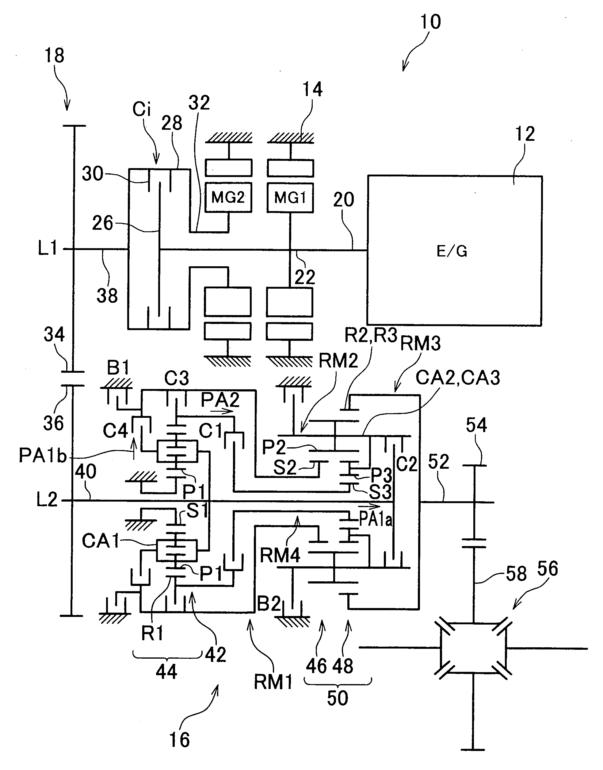
[0039]FIG. 1 is a skeleton view of the structure of a vehicular drive system (hereinafter simply referred to as “drive system”) 10 to which the invention has been applied. This drive system 10 includes an engine 12 and a transmission case 14 which is a non-rotating member mounted to a vehicle body. The transmission case 14 houses a first motor-generator MG1 which serves as a first electric motor, a second motor-generator MG2 which serves as a second electric motor, a lock-up clutch Ci, a stepped automatic transmission (hereinafter simply referred to as “automatic transmission”) 16 which serves as a transmission, and a counter gear set 18 which serves as power transmitting means, and the like.

[0040] The first motor-generator MG1, the second motor-generator MG2, and the lock-up clutch Ci are all arranged in that order from the upstream side of the power transmi...


PUM


Abstract

A second electric motor is arranged on a first axis on which an output shaft of the engine is arranged, a transmission is arranged on a second axis which is parallel with the first axis, and a clutch is arranged on the first axis to selectively connect and disconnect the second electric motor and the transmission to and from the engine. Power on the first axis is transmitted to an input shaft of the transmission via a power transmitting mechanism.

Description

INCORPORATION BY REFERENCE [0001] The disclosure of Japanese Patent Application No. 2004-329201 filed on Nov. 12, 2004 including the specification, drawings and abstract is incorporated herein by reference in its entirety. BACKGROUND OF THE INVENTION [0002] 1. Field of the Invention [0003] The invention relates to a vehicular drive system which is used in a vehicle such as an automobile. [0004] 2. Description of the Related Art [0005] A vehicular drive system is known which includes an engine, two electric motors, a transmission, and a clutch that is operatively connected to the engine and can selectively connect and disconnect the transmission to and from the engine. One example of such a vehicular drive system is disclosed in US Patent Application Publication No. 2003 / 0127262A1. In this type of vehicular drive system, the clutch is provided in place of a fluid power transmitting device such as a torque converter, and the transmission shifts speeds while an input shaft thereof is o...

Claims


Application Information

Patent Timeline
IPC IPC(8): B60K17/35B60K6/26B60K6/38B60K6/40B60K6/442B60K6/547B60K17/02B60K17/04B60L50/16F16H3/62F16H3/66
CPCF16H2200/2097Y02T10/642Y02T10/6234B60K1/02B60K6/365B60K6/387B60K6/40B60K6/442B60K6/48B60K6/547F16H3/663F16H3/666F16H2200/006F16H2200/0086F16H2200/2007F16H2200/2023B60L1/003B60L1/02B60L7/12B60L11/123B60L11/14B60L15/2009B60L2240/12B60L2240/14B60L2240/421B60L2240/423B60L2240/425B60L2240/441B60L2240/443B60L2240/445B60L2240/486B60L2250/24B60L2250/26Y10S903/917Y02T10/7077Y02T10/7275Y02T10/6217Y02T10/6221Y02T10/72B60L50/61B60L50/16Y02T10/62Y02T10/64Y02T10/7072Y02T10/70
Inventor KAMADA, ATSUSHITABATA, ATSUSHIINOUE, YUJIIBARAKI, RYUJI
Owner TOYOTA JIDOSHA KK
Why Eureka
Try Eureka