Technique for enhanced quality high resolution 2D imaging of ground moving targets

a 2d imaging and high resolution technology, applied in the field of moving target detection, can solve problems such as unsatisfactory extended target acquisition tim

Active Publication Date: 2006-05-25
RAYTHEON CO
View PDF12 Cites 17 Cited by
  • Summary
  • Abstract
  • Description
  • Claims
  • Application Information

AI Technical Summary

Problems solved by technology

Sometimes, resolving the uncertainty in position of a moving target with respect to the SAR map, r

Method used


Image

  • Technique for enhanced quality high resolution 2D imaging of ground moving targets
  • Technique for enhanced quality high resolution 2D imaging of ground moving targets
  • Technique for enhanced quality high resolution 2D imaging of ground moving targets

Examples


Embodiment Construction

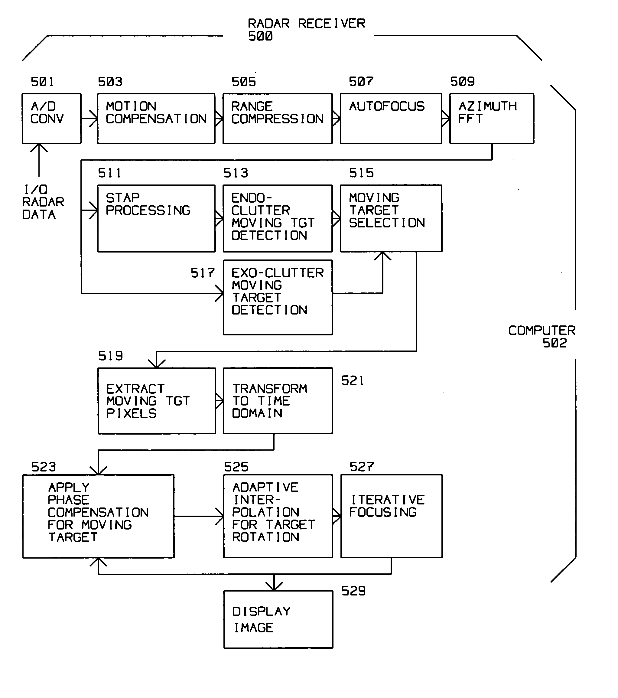
[0019] The present invention describes an apparatus and method for detecting moving targets within a SAR image.

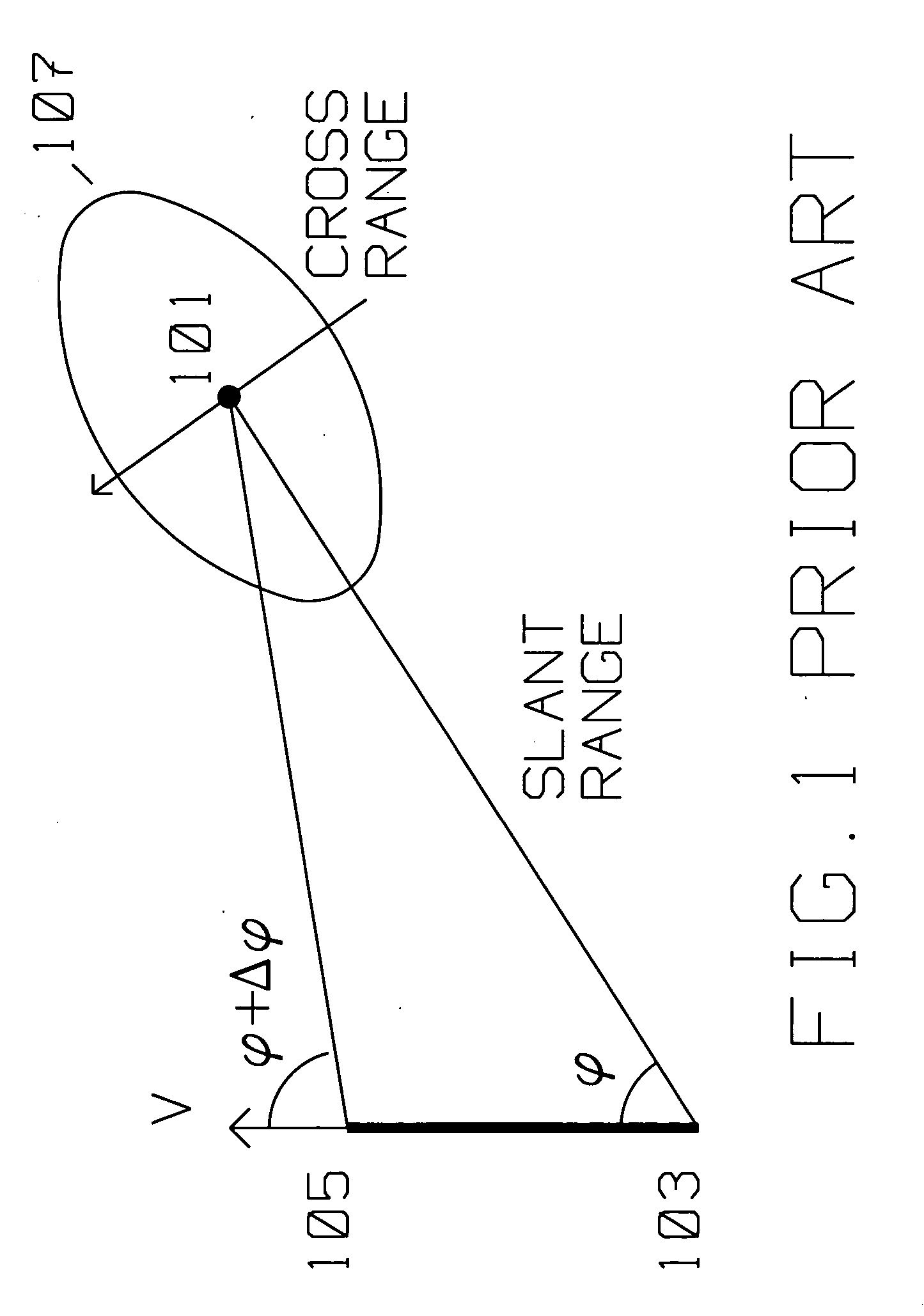
[0020]FIG. 1 shows the typical geometric relationship between a moving platform carrying a radar transmitter / receiver using Synthetic Aperture (SAR) spotlight methods and target area 101 to be imaged by said radar transmitter / receiver. The moving platform is initially at position 103, travels with velocity V in the direction shown to position 105. In SAR spotlight mode, the SAR antenna is actively oriented towards scatterer 101 as the platform moves with respect to scatterer 101 with velocity V. The moving platform moves from position 103 to position 105, while adjusting the side looking angle from φ to φ+Δφ for spotlight mode so that the antenna keeps illuminating target area 101. Antenna illumination with radar energy covers area 107 during the array length, and includes target area 101. Similarly, the antenna receive pattern covers area 107, and includes target area 101...


PUM


Abstract

A radar receiver on a moving platform images a moving target and non-moving clutter using a single SAR array. The radar receiver converts the radar returns into digital radar returns and motion compensates the digital radar returns with respect to a reference, then applies further phase compensation to obtain an autofocused synthetic aperture image. A plurality of moving target pixels descriptive of the moving target are detected within the autofocused synthetic aperture image. The plurality of moving target pixels are transformed from the autofocused image to the time domain. The time domain moving target data is focused by iteratively applying a phase compensation to the time domain moving target data.

Description

[0001] This application is a continuation in part of U.S. patent and Trademark application Ser. No. 10 / 996,024, filed Nov. 23, 2004, titled “Technique for Cancellation of Elevated Clutter for the Detection of Fixed and Ground Moving Targets Under Trees”.BACKGROUND OF THE INVENTION [0002] 1. Field of Invention [0003] This invention is in the field of moving target detection for use with radar imaging and / or target detection using a single channel receiver. [0004] 2. Description of the Related Art [0005] Synthetic Aperture Radar (SAR) radar is used for ground mapping as well as target identification. The general principle behind SAR is to coherently combine the amplitude and phase information of radar returns from a plurality of sequentially transmitted pulses from a relatively small antenna on a moving platform. [0006] The plurality of returns creating a SAR image generated by the transmitted pulses along a known path of the platform make up an array. During the array, amplitude as w...

Claims


Application Information

Patent Timeline
IPC IPC(8): G01S13/90
CPCG01S13/90G01S13/9019
Inventor KRIKORIAN, KAPRIEL V.ROSEN, ROBERT A.
Owner RAYTHEON CO
Why Eureka
Try Eureka