

Dual modality tomography apparatus with a patient support device
a tomography apparatus and support device technology, applied in the field of tomography apparatus, can solve the problem of high cost and inability to achieve such a stiffness of the support pla
- Summary
- Abstract
- Description
- Claims
- Application Information
AI Technical Summary
Benefits of technology
Problems solved by technology
Method used
Image

Examples
Embodiment Construction
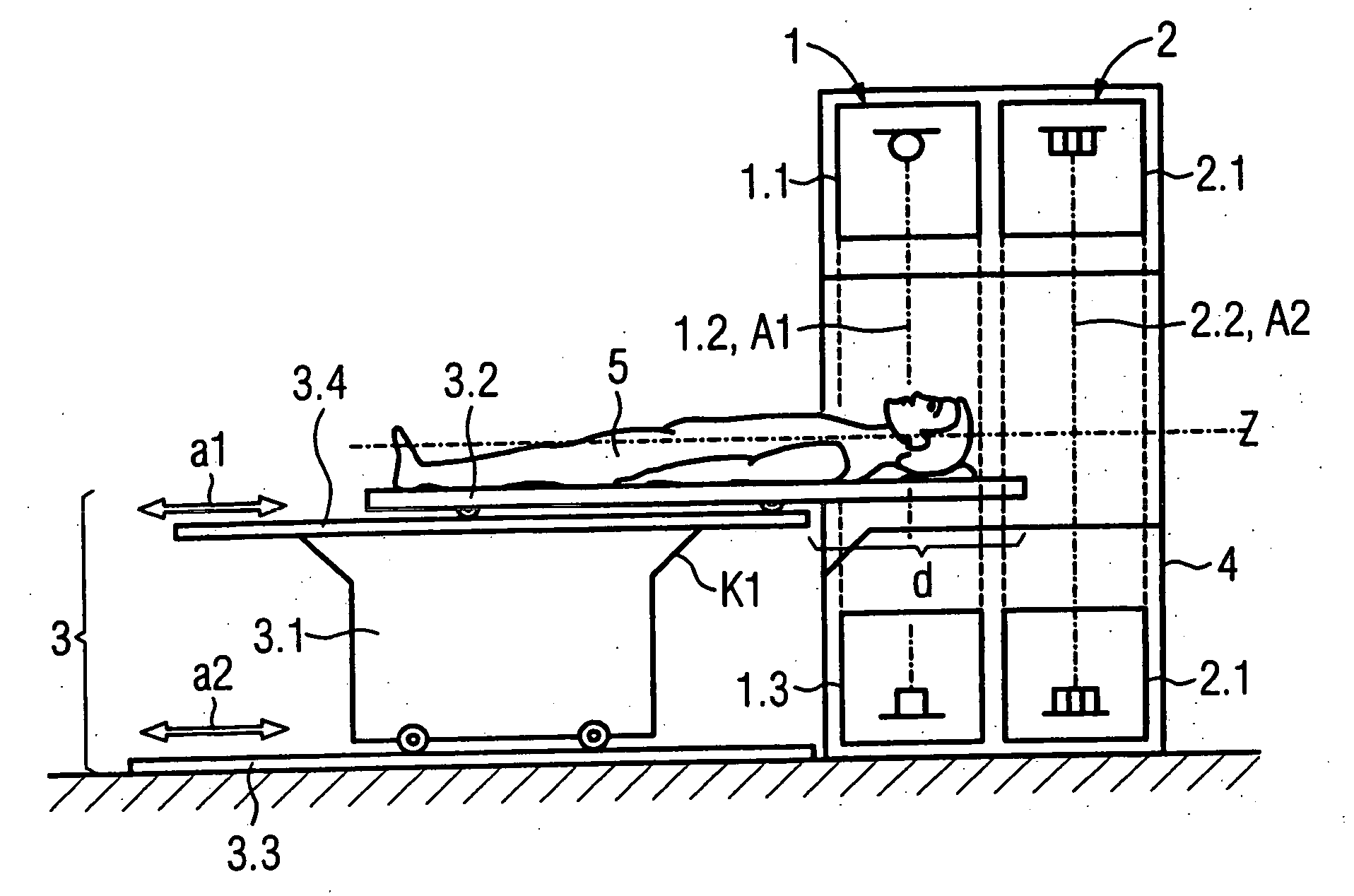
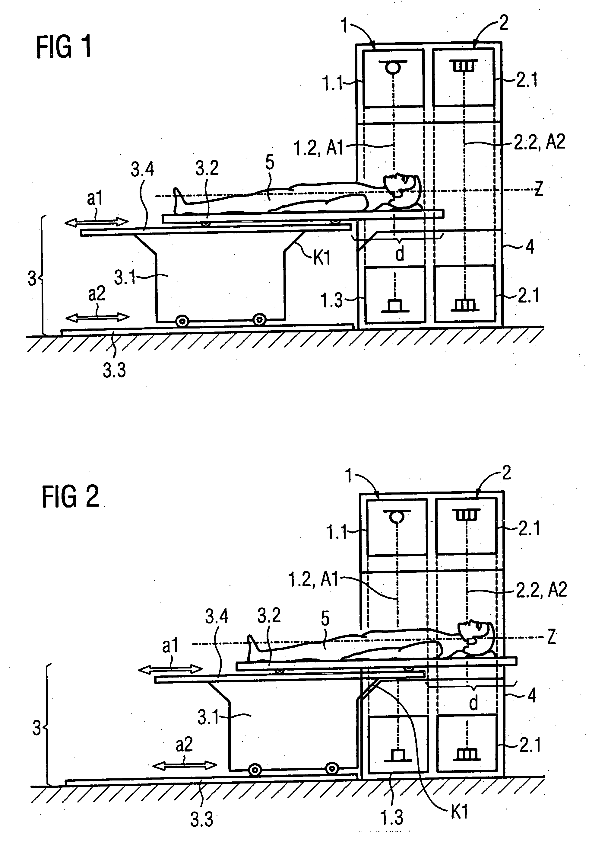
[0020] In a side view, FIG. 1 shows an inventive tomography apparatus with two acquisition systems 1, 2 arranged one after the other in the displacement directions a1, a2, and a support device 3 (which can be displaced in the displacement directions a1, a2) in a first acquisition position A1 relative to the first acquisition system 1. In the shown example the first acquisition system is a CT acquisition system 1 and the second acquisition system is a PET acquisition system 2. The support device has a base 3.1 that can be displaced on rails 3.3 relative to the floor and a support plate 3.2 (that can be displaced relative to the base 3.1 and likewise supported on rails 3.4 in this example) for supporting a subject, in this case a patient 5.
[0021] The CT acquisition system 1 has an x-ray radiator 1.1 and a CT detector 1.3 mounted opposite one another on a rotary frame (not shown) such that, in operation of the CT acquisition system 1, an x-ray beam emanating from a focus of the x-ray ...
PUM
 Abstract
Description
Claims
Application Information